General Notice
When using this document, keep the following in mind:
1. This document is confidential. By accepting this document you acknowledge that you are bound
by the terms set forth in the non-disclosure and confidentiality agreement signed separately and /in
the possession of SEGA. If you have not signed such a non-disclosure agreement, please contact
SEGA immediately and return this document to SEGA.
2. This document may include technical inaccuracies or typographical errors. Changes are periodi-
cally made to the information herein; these changes will be incorporated in new versions of the
document. SEGA may make improvements and/or changes in the product(s) and/or the
program(s) described in this document at any time.
3. No one is permitted to reproduce or duplicate, in any form, the whole or part of this document
without SEGA's written permission. Request for copies of this document and for technical
information about SEGA products must be made to your authorized SEGA Technical Services
representative.
4. No license is granted by implication or otherwise under any patents, copyrights, trademarks, or
other intellectual property rights of SEGA Enterprises, Ltd., SEGA of America, Inc., or any third
party.
5. Software, circuitry, and other examples described herein are meant merely to indicate the character-
istics and performance of SEGA's products. SEGA assumes no responsibility for any intellectual
property claims or other problems that may result from applications based on the examples
describe herein.
6. It is possible that this document may contain reference to, or information about, SEGA products
(development hardware/software) or services that are not provided in countries other than Japan.
Such references/information must not be construed to mean that SEGA intends to provide such
SEGA products or services in countries other than Japan. Any reference of a SEGA licensed prod-
uct/program in this document is not intended to state or simply that you can use only SEGA's
licensed products/programs. Any functionally equivalent hardware/software can be used instead.
7. SEGA will not be held responsible for any damage to the user that may result from accidents or any
other reasons during operation of the user's equipment, or programs according to this document.
(11/2/94- 002)
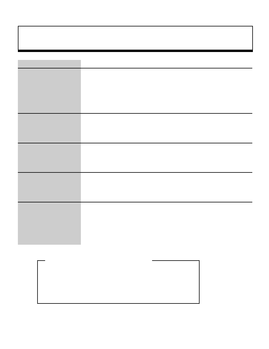
This is a preliminary document
and is subject to change without notice. This document could include
technical inaccuracies or typographical errors. Changes are periodically made to the information
herein; these changes will be incorporated in official versions of the publication.
NOTE: A reader's comment/correction form is provided with this
document. Please address comments to :
SEGA of America, Inc., Technical Translation and Publications Group
(att. Document Administrator)
150 Shoreline Drive, Redwood City, CA 94065
SEGA may use or distribute whatever information you supply in any way
it believes appropriate without incurring any obligation to you.
|

SGL Developer's Manual
Reference
Function Reference
Structure Reference
Appendix
Memory Map
|

SGL Reference
Function Reference
The Sega Saturn Graphics Library (SGL) is a C language function library
assembled for software development support for the Sega Saturn system.
The SGL is ideal for the development of software that uses 3D graphics.
Because careful and rigorous consideration was given to the selection of the
types of functions for the SGL, the total number is not that large. when
used in combination, however, these functions are more than sufficient for
the development of 3D games and similar software. In fact, the design
concept behind the creation of the SGL was to permit fast and flexible
software development through the use of combinations of simple modules.
We hope that you will find that the SGL opens up the exciting world of the
Sega Saturn system.
Sega Enterprises, Ltd.
Yu Suzuki
|
Graphics function
1
void
slLight
Light source setup
Format
void slLight(light)
VECTOR light;
Parameters
light
Light source vector
Function
This function sets up the light source.
For the parameters, substitute the vector value (unit vector) that indicates the
direction of the light rays.
Return Value
None
Remarks
The light source vector must be specified as a unit vector. Assuming the size of
the light source vector were to exceed "1", an overflow would occur and the
polygon surface color would not be displayed properly.
In addition, if the scaling operation is being performed on the current matrix, it is
important to realize that the normal vector of the polygon is also affected, and
thus the brightness will change accordingly.
Refer to: Chapter 3, "Light Sources
slLight
|
Graphics function
2
void
slperspective
Perspective transformation table setup
Format
void slPerspective(pers)
ANGLE pers;
Parameters
pers
Perspective angle
Range: 10 to 160 (unit: DEG
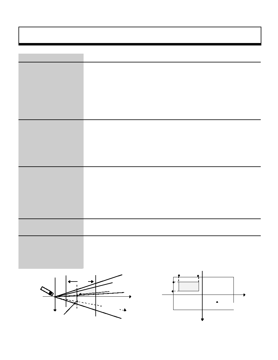
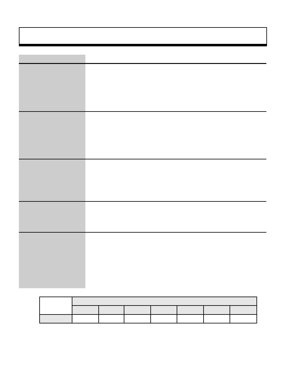
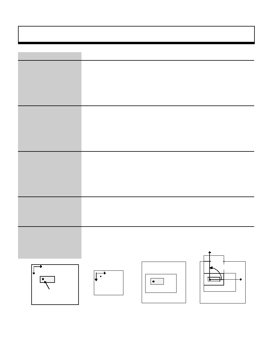
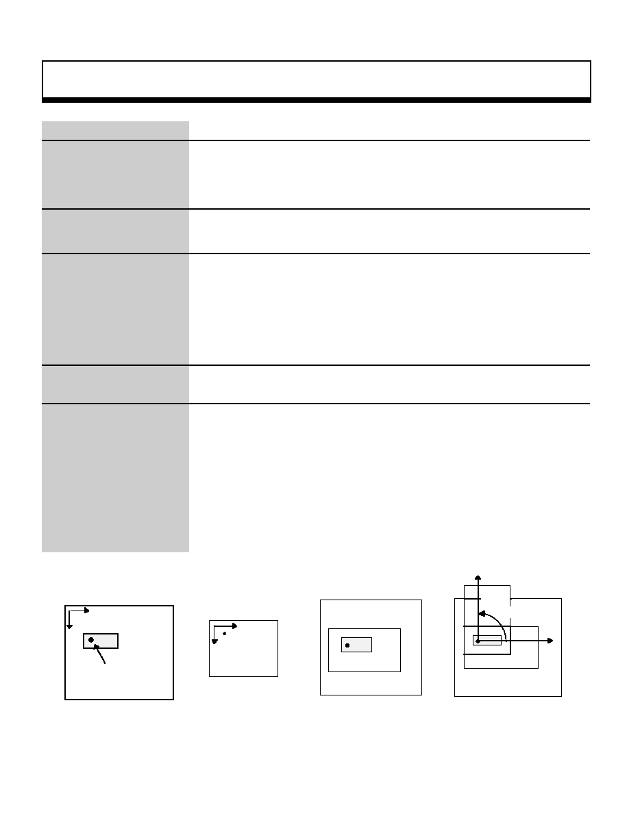
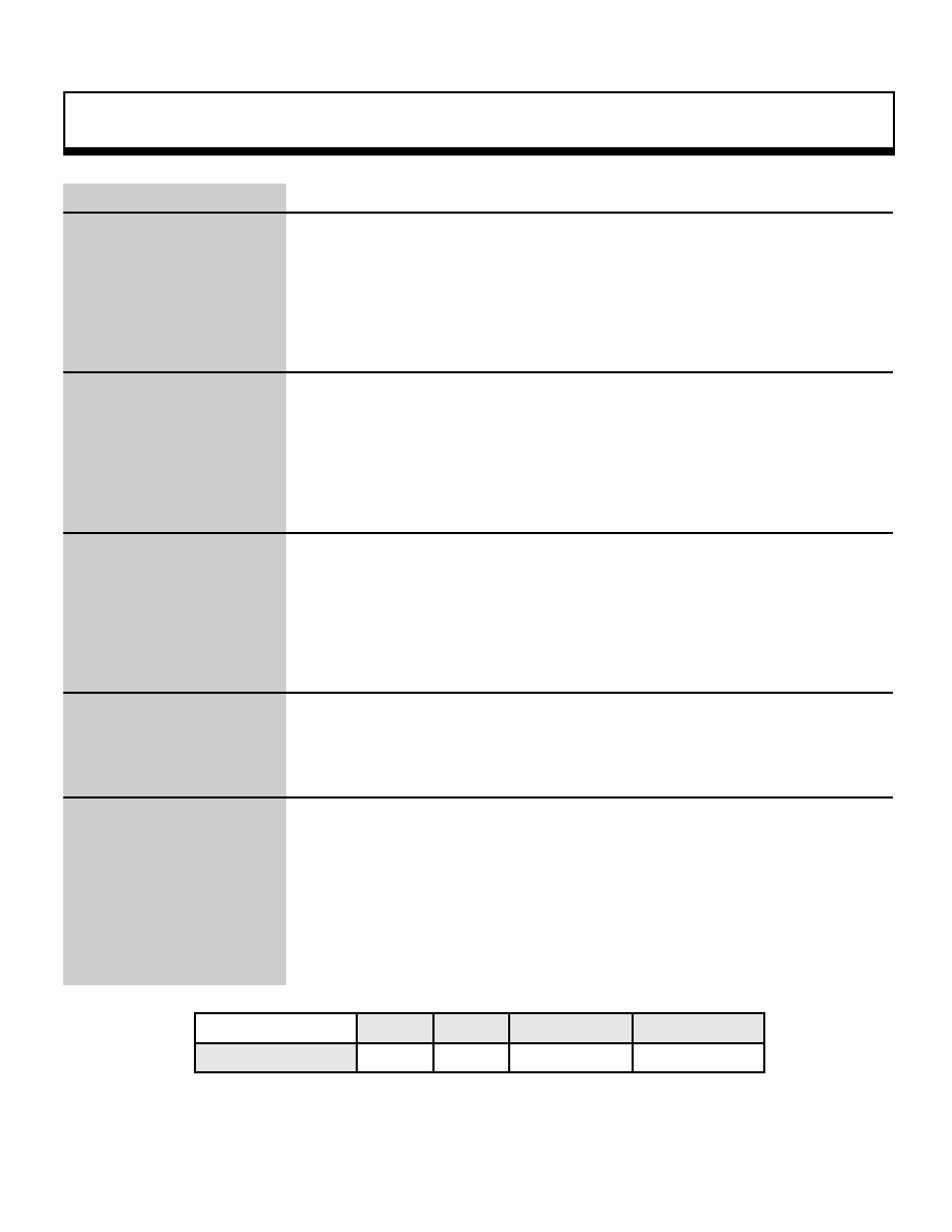
Function
This function sets the constant for the distance to the screen, which is used in
perspective transformations. The perspective angle parameter determines the
angle corresponding to the width of the screen.
Because this function also sets the parameters for the rotating scroll, execute
slRpasaInitSet() before calling this function when using the rotating scroll.
Return Value
None
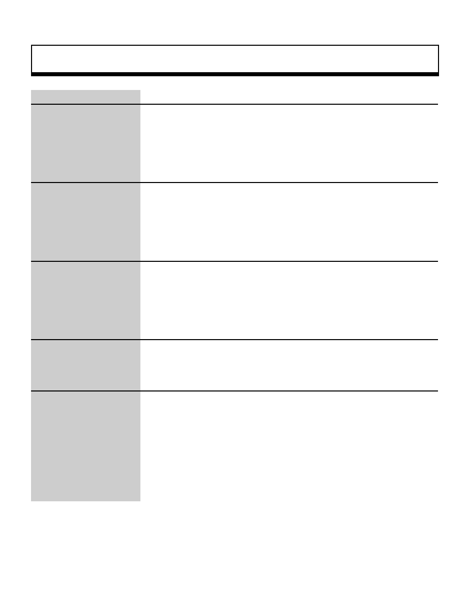
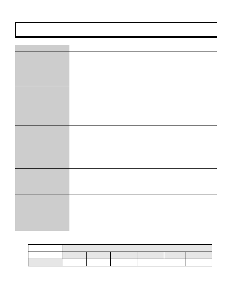
Remarks
The functions "slWindow" and "slZdispLevel" in combination with "slPerspective"
completely determine the viewing volume. The diagram below illustrates the
concepts behind perspective transformation.
Refer to: Chapter 4, "Coordinate Transformation"
slPerspective
Forward boundary surface
Projection surface
Perspective
angie:60¡
Clipping boundary
X
Y
Rear boundary
surface
Viewing volume
|
Graphics function
3
void
slPutPolygon
Polygon model drawing
Format
void slPutPolygon(pat)
PDATA *pat;
Parameters
pat
Starting address of area where polygon data is stored
Function
This function draws the polygon model specified by the parameter.
The polygon model is affected by the parallel shift component and rotation
component of the current matrix, and is drawn on the screen using perspective
transformations.
Return Value
None
Remarks
The polygon data is defined as a PDATA structure.
A PDATA structure includes the polygon vertex list, the number of vertices, the
face list, the number of faces, and the face attribute information.
For details, refer to "Structure Reference: PDATA Structure" and Chapter 2,
"Graphics," in the Programmer's Tutorial.
PDATA<Label name>={
point_PLANE1.
/* vert,ex list */
sizeof(point_PLANE1)/SIZEOF(POINT),
/* number of vertices */
polygon_PLANE1,
/* face list */
sizeof(point_PLANE1)/SIZEOF(POLYGON),
/* number of faces */
attribute_PLANE1
/* face attribute list */
};
Note: The PDATA structure is defined in "sl_def.h".Refer to: Chapter 2, "Graphics"
slPutPolygon
_oe Polygon data structure _oe
|
Graphics function
4
void
slWindow
Various window settings
Format
void slWindow
left , top , right , bottom , Zlimit , centx , centy
Sint16 left;
Sint16 top;
Sint16 right;
Sint16 bottom;
Sint16 Zlimit;
Sint16 centx;
Sint16 centy;
Parameters
left
X coordinate of upper-left corner of window (screen coordinate system)
top
Y coordinate of upper-left corner of window (screen coordinate system)
right
X coordinate of lower-right corner of window (screen coordinate system)
bottom Y coordinate of lower-right corner of window (screen coordinate system)
Zlimit
Distance to rear boundary surface of window
centx
X coordinate of vanishing point
centy
Y coordinate of vanishing point
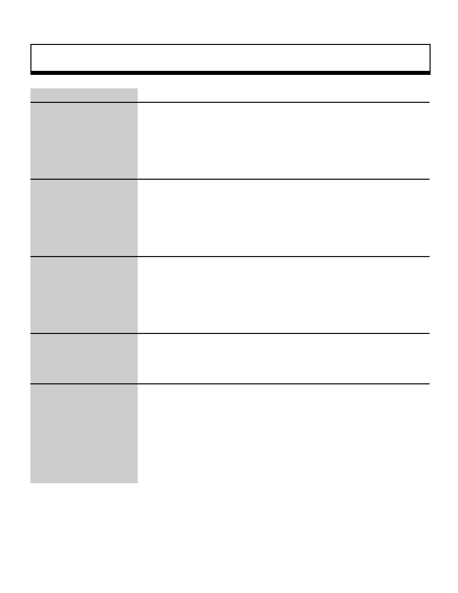
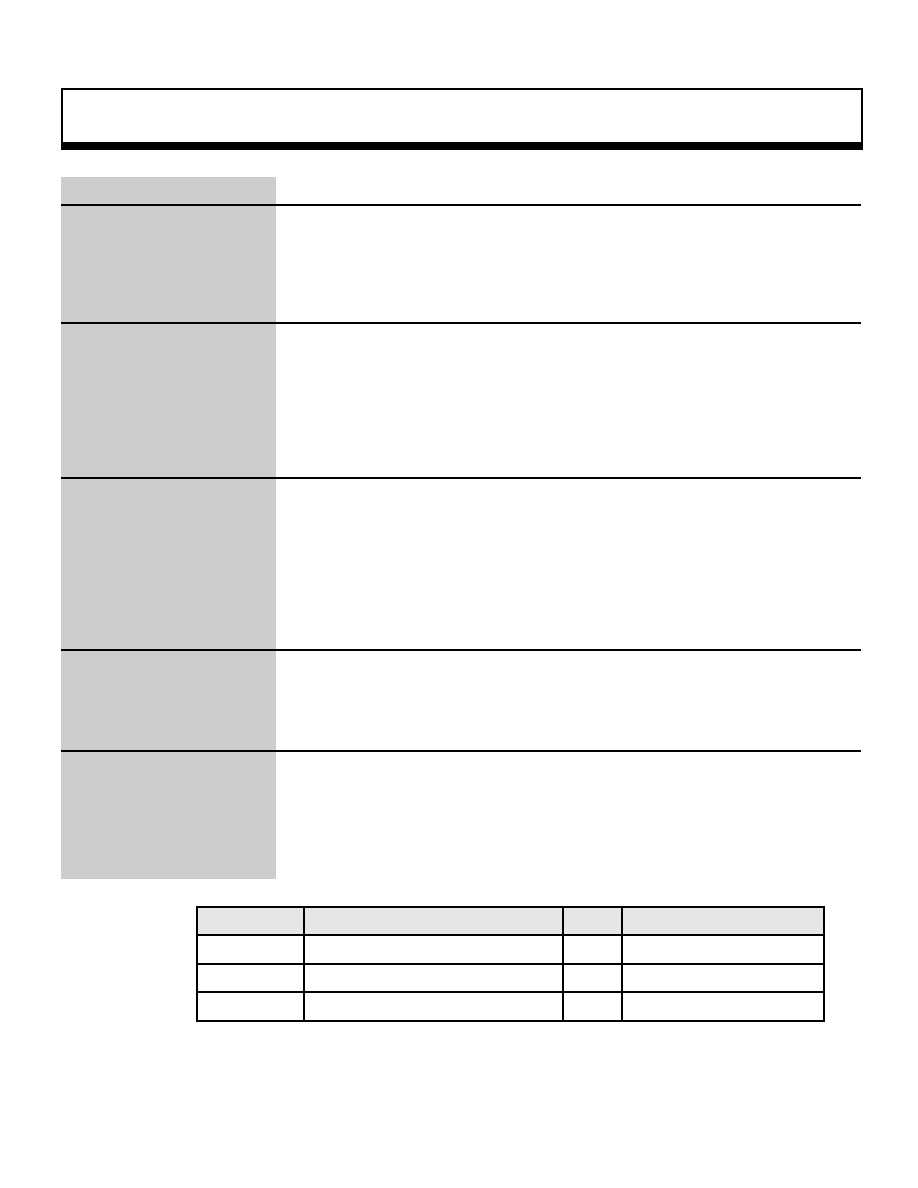
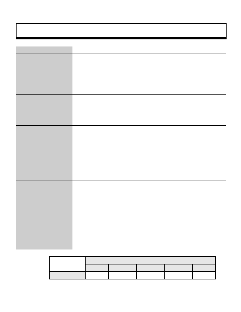
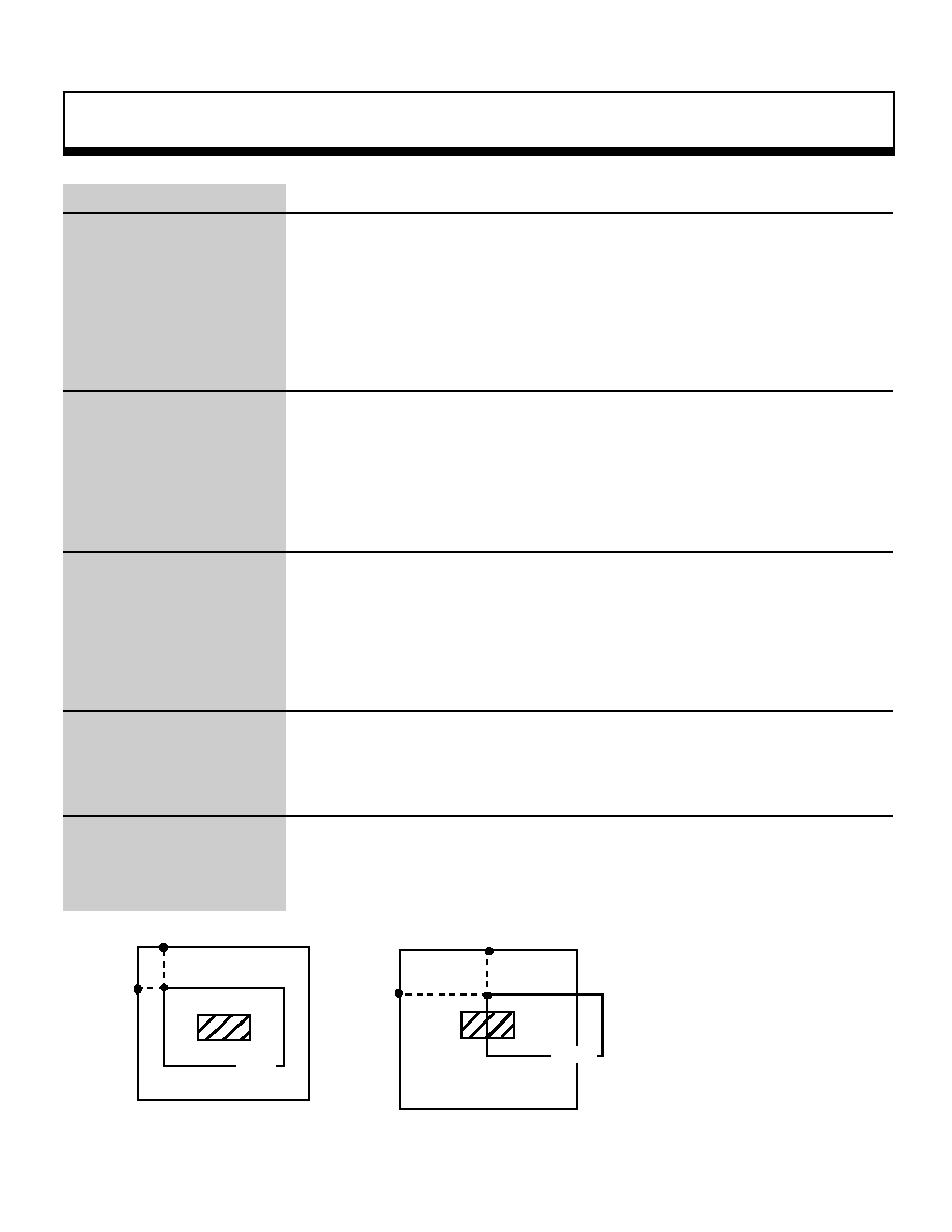
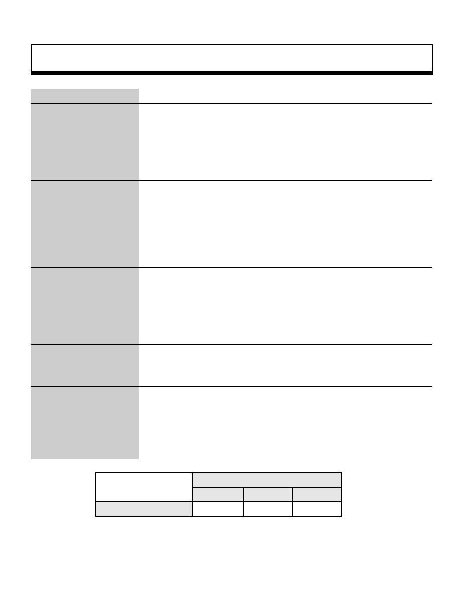
Function
This function sets up windows that limits the display of sprites and
polygons.
"Window" is the name of a rectangular area set up on the screen; two windows
can be set up on the screen at one time.
Polygons and sprites can be set to be displayed or not displayed when they are
inside or outside of a window.
For the parameters, substitute the X and Y screen coordinates defining the area
of the window, the Z coordinate that indicates the distance to the rear boundary
surface of the display, and the X and Y screen coordinates of the vanishing point.
Return Value
None
Remarks
Polygons and sprites are affected by windows that are set up before the polygon
or sprite is drawn.
In the SGL, a window that is the same size as the screen is set up as a default
window; if the function "slWindow" is not executed, the drawing of polygons and
sprites is affected by this default window.
Note: "left", "top", "right", "bottom", "CENTER_X", and "CENTER_Y" refer to the X and Y screen coordinates
.
Refer to: Chapter 4, "Coordinate Transformation"
slWindow
Zlimit
forward boundary surface
Rear boundary surface
Windouw boundary
(left, top, right,
Z
Z
Y
Line of sight
Projection surface
Viewpoint
(CENTER_X,CENTER_Y)
( 0 , 0 )
left
right
top
bottom
Projection surface
(CENTER_X, CNTER_Y)
( 319, 223 )
Window
Y
X
|

Graphics function
5
void
slZdspLevel
Display level specification
Format
void slZdspLevel(level)
Uint16 level;
Parameters
level
Display level
1: Display from 1/2
2: Display from 1/4
3: Display from 1/8
Note: For an explanation of the display level, refer to the diagram shown
below.
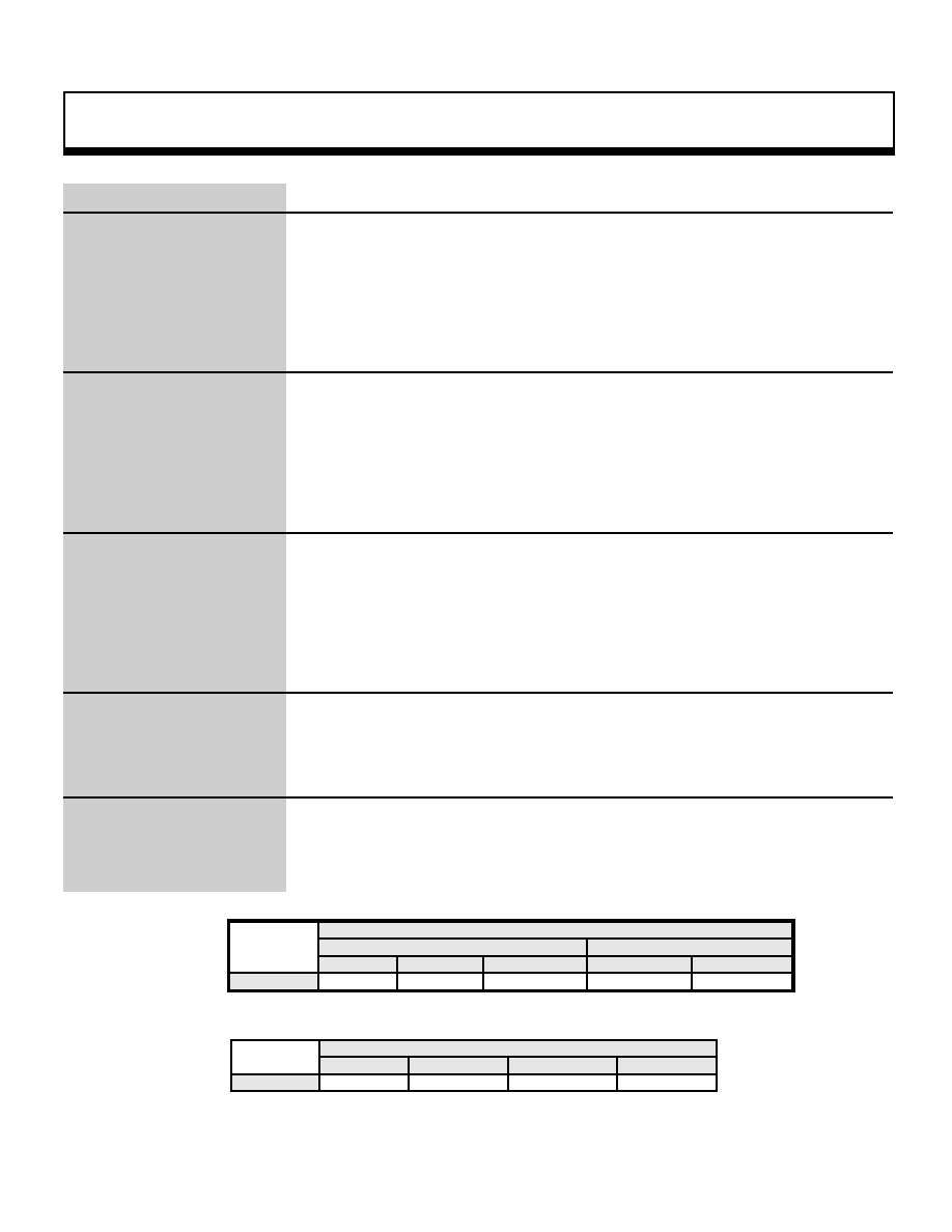
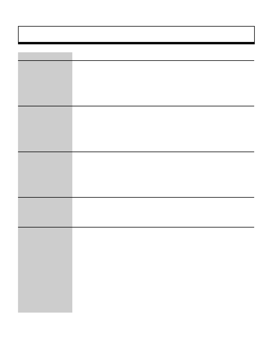
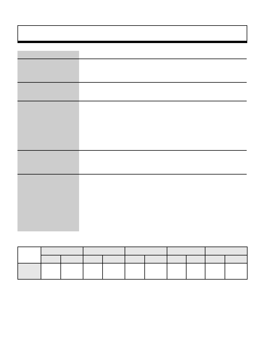
Function
This function specifies how far in front of the projection surface to actually project
(the front boundary surface).
Return Value
None
Remarks
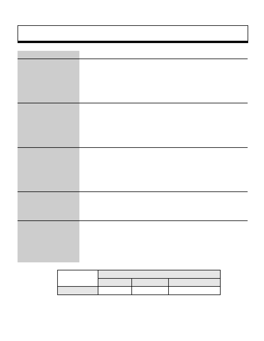
The distance from the forward boundary surface to the rear boundary surface is
the "Zlimit".
The "Zlimit" is specified by the "slWindow" function.
During system initialization, the display level is set to "1/2".
Refer to: Chapter 4, "Coordinate Transformation"
slZdspLevel
Rear boundary surface
Viewing volume
(when ScreenDist=1/2)
Projection surface
Forward boundary surface
Viewpoint
1/2
1/4
1/8
Display level: Specifies the distance between the viewpoint and the forward
boundary surface in terms of the number of times the distance to
theprojection surface is divided.
Zlimit: Distance between the forward boundary surface and the rear boundary
surface
|

Scroll Function
6
void
sllMapRA
RGB map setup (using rotation parameters A)
Format
void sl1MapRA(a)
void *a ;
Parameters
a
Starting address in VRAM of pattern name data table for rotation
parameters A
Function
This function sets up the rotating scroll map (using rotation parameters A). For the
parameter, substitute the starting address in VRAM of the pattern name data table
to be registered in the map register and the map offset register. The data table
uses 16 pages, starting from the specified address.
Return Value
None
Remarks
Refer to: Chapter 8, "Scrolls"
sl1MapRA
|

Scroll Function
7
void
sllMapRB
RGB map setup (using rotation parameters B)
Format
void sl1MapRB(b)
void *b;
Parameters
b
Starting address of in VRAM pattern name data table for rotation
parameters B
Function
This function sets up the rotating scroll map (using rotation parameters B). For the
parameter, substitute the starting address in VRAM of the pattern name data table
to be registered in the map register and the map offset register. The data table
uses 16 pages, starting from the specified address.
Return Value
None
Remarks
Refer to: Chapter 8, "Scrolls"
sl1MapRB
|
Scroll Function
8
void
sl16MapRA
RBG0 map setting (using rotation parameters A)
Format
void sl16MapRA(map [16])
Uint8 map [16] ;
Parameters
map[16]
Map number for 16 pages
Function
This function sets up a rotating scroll map consisting of 16 pages (using rotation
parameters A).
Return Value
None
Remarks
This function sets the map number for 16 pages for the matrix passed as the
parameter.
ABCD
EFGH
IJKL
MNOP
The matrix is set up for the pages in the 4 x 4 configuration shown above in the
sequence A, B, C... N, O, P.
Refer to: Chapter 8, "Scrolls"
sl16MapRA
|
Scroll Function
9
void
slBackColSet
Background screen single-color setup
Format
void slBack1ColSet(colptr , rgbptr)
void *colptr ; Uint16 rgbptr ;
Parameters
colptr
Starting address in VRAM where the background color is stored
rgbptr
Color data, 5 bits for each of red, green, and blue
Function
This function sets up the background screen.
The "background screen" is the graphics screen that is displayed in the
background in those areas where absolutely nothing else is displayed.
Return Value
None
Remarks
Although the background screen color specification is made with the parameter
"rgbptr", refer to the RGB mode color sample "RGB_flag" in the include file
"sl_def.h" for the substitution values.
¥
RGB mode color sample
¥
#define
CD_Black
(0<<10) : (0<<5) : RGB_Flag
#define
CD_DarkRed
(0<<10) : (0<<5) : RGB_Flag
#define
CD_DarkGreen
(0<<10) : (0<<5) : RGB_Flag
_ç
#define
CD_Purple
(0<<10) : (0<<5) : RGB_Flag
#define
CD_Margenta
(0<<10) : (0<<5) : RGB_Flag
#define
CD_White
(0<<10) : (0<<5) : RGB_Flag
Note: The above values are defined in "sl_def.h",provided with the system.
Refer to: Chapter 8, "Scrolls"
slBack1ColSet
|
Scroll Function
10
void
slBitMapNbg0,1
Bitmap mode setting
Format
void slBitMapNbg0(col_type,bmsize)
void slBitMapNbg1(col_type,bmsize)
Uint16col_type;
Uint16bmsize;
Parameters
col_type
Color mode flag
bmsize VRAM Bitmap size flag
Function
This function changes the screen to bitmap mode, and sets the color mode and
bitmap size.
Return Value
None
Remarks
Refer to the tables below for the flags to be substituted for the parameters. Note,
however, the 16.77 million color specification can only be specified for NBG0.
Color mode flag
Palette format
RGB format
16 colors
256 colors
2048 colors
32,768 colors
16.77 million colors
Substitution value
COL_TYPE_16
COL_TYPE_256
COL_TYPE-2048
COL_TYPE_32768
COL_TYPE_1M
Note: In color RAM mode 0 or 2, "2048 colors" becomes "1024 colors."
Bitmap size
512 x 256 (H x V))
512 x 512 (H x V)
1024 x 256 (H x V))
1024 x 512 (H x V)
Substitution value
BM_512x256
BM_512x512
BM_1024x256
BM_1024x512
Note: The values in the above table are defined in "sl_def.h", provided with the system.
Refer to: HARDWARE MANUAL vol. 2 (VDP2)
slBitMapNbg0, 1
|
Scroll Function
11
void
slBMPaletteNbg0,1
Bitmap screen palette number setting (NBG)
Format
void slBMPaletteNbg0(pal)
void slBMPaletteNbg1(pal)
Uint16 pal;
Parameters
pal
Palette number (0 to 7)
Function
This function sets the palette number when displaying the bitmap screen in palette
format.
Return Value
None
Remarks
Refer to: HARDWARE MANUAL vol. 2 (VDP2)
slBMPaletteRbg0,1
|

Scroll Function
12
void
slCharNbg0,1,2,3
NBG character control setup
Format
void slCharNbg0(col_type , chara_size)
void slCharNbg1(col_type , chara_size)
void slCharNbg2(col_type , chara_size)
void slCharNbg3(col_type , chara_size)
Uint16 col_type ,
Uint16 chara_size ;
Parameters
col_type
flag for the specification of the number of colors for the scroll
chara_size
flag for the character size specification
Function
This function sets the character size and the number of colors used on normal
scrolls NBG0, NBG1, NBG2, and NBG3.
Refer to the table below for the substitution values for the parameters.
Return Value
None
Remarks
When the color RAM mode is 0 or 2, the 2048-color specification becomes 1024
colors. In addition, the maximum number of colors that can be specified differs
according to the scroll screen type.
Number of character colors
Character size
Palette format
RGB format
16 colors
256 colors
2048 colors
32,768 colors
16.77 million colors
1 x 1
2 x 2
Substitution value
COL_TYPE_16
COL_TYPE_256
COL_TYPE_2048
COL_TYPE_32768
COL_TYPE_1M
CHAR_SIZE_1x1
CHAR_SIZE_2x2
Note 1:In color RAM mode 0 or 2, "2048 colors" becomes "1024 colors."
Note 2:The values in the above table are defined in "sl_def.h", provided with the system.
Refer to: Chapter 8, "Scrolls"
slCharNbg0,1,2,3
|
Scroll Function
13
void
slCharRbg0
RBG character control setup
Format
void slCharRbg0(col_type , chara_size)
Uint16 col_type ,
Uint16 chara_size ;
Parameters
col_type
flag for the specification of the number of colors for the scroll
chara_size
flag for the character size specification
Function
This function sets the character size and the number of colors used on rotating
scroll RBG0.
Refer to the table below for the substitution values for the parameters.
Return Value
None
Remarks
When the color RAM mode is 0 or 2, the 2048-color specification becomes 1024
colors.
Number of character colors
Character size
Palette format
RGB format
16 colors
256 colors
2048 colors
32,768 colors
16.77 million colors
1 x 1
2 x 2
Substitution value
COL_TYPE_16
COL_TYPE_256
COL_TYPE_2048
COL_TYPE_32768
COL_TYPE_1M
CHAR_SIZE_1x1
CHAR_SIZE_2x2
Note 1:In color RAM mode 0 or 2, "2048 colors" becomes "1024 colors."
Note 2:The values in the above table are defined in "sl_def.h", provided with the system
.
Refer to: Chapter 8, "Scrolls"
slCharRbg0
|
Scroll Function
14
void
slColOffsetOn
Color offset enable setting
Format
void slColOfsetOn(flag)
Uint16 flag ;
Parameters
flag
Screen specification
Function
This function sets the screen that will be affected by the color offset set by the
function "slColOfsetA".
The "or" operator ("|") can be used to link together multiple parameters so that
multiple screens can be set simultaneously.
Return Value
None
Remarks
For the parameter, substitute the value from the table shown below corresponding
to the scroll screen to be registered.
Scroll screen being registered
NBG0
NBG1
NBG2
NBG3
RBG0
BACK
SPRITE
Substitution value
NBG0ON
NBG1ON
NBG2ON
NBG3ON
RBG0ON
BACKON
SPRON
Note: The values in the above table are defined in "sl_def.h", provided with the system.
Refer to: Chapter 8, "Scrolls"
slColOffsetOn
|
Scroll Function
15
void
slColOffsetBUse
Color offset select
Format
void slColOfsetBUse(flag)
Uint16 flag;
Parameters
flag
Screen
Function
This function sets the screen that will be affected by the color offset set by the
function "slColOfsetB".
The "or" operator ("|") can be used to link together multiple parameters so that
multiple screen can be set simultaneously.
Return Value
None
Remarks
For the parameter, substitute the value from the table shown below corresponding
to the scroll screen to be registered.
Scroll screen being registered
NBG0
NBG1
NBG2
NBG3
RBG0
BACK
SPRITE
Substitution value
NBG0ON
NBG1ON
NBG2ON
NBG3ON
RBG0ON
BACKON
SPRON
Note: The values in the above table are defined in "sl_def.h", provided with the system.
Refer to: Chapter 8, "Scrolls"
slColOffsetBUse
|

Scroll Function
16
void
slColOffsetA,B
Color offset setting
Format
void slColOfsetA(r , g , b)
void slColOfsetB(r , g , b)
Sint16 r ;
Sint16 g ,
Sint16 b ;
Parameters
r
Red offset value (signed 9 bits)
g
Green offset value (signed 9 bits)
b
Blue offset value (signed 9 bits)
Function
These functions set the color offset values for red green and blue. The function
"slColOfsetA" sets the offset values used for color offsets A, and the function
"slColOfsetB" sets the offset values used for color offsets B.
Return Value
None
Remarks
To set a negative value for an offset value, substitute the complement of the
absolute value of that number.
Color offset processing is executed after color operation processing.
Refer to: Chapter 8, "Scrolls"
slColOffsetA,B
|
Scroll Function
17
void
slColorCalc
Color calculation control setting
Format
void slColorCalc( flag )
Uint16 flag ;
Parameters
flag
Color calculation control parameter
Function
This function sets parameters for color calculations, etc.
Return Value
None
Remarks
For the parameters, substitute the values in the table below according to the
functions being used. Refer to "HARDWARE MANUAL vol. 2" (VDP2 User's
Manual: p. 241) for details.
Calculation method
:[CC_RATE | CC_ADD] |
Image for which calculation is specified
:[CC_TOP | CC_2ND] |
Extended color operations
:[CC_EXT] |
Registered screen
:[NBG0ON|NBG1ON|NGB2ON|NBG3ON|RBG0ON|LNCLON|SPRON] |
Refer to: Chapter 8, "Scrolls"
slColorCalc
_oe ColorCalc substitution values
_oe
|
Scroll Function
18
void
slColorCalcOn
Color calculation control enable setting
Format
void slColorCalcOn( flag )
Uint16 flag ;
Parameters
flag
Specifies the screens on which color calculation is performed
Function
This function sets the screen that is affected by color calculation control.
The "or" operator ("|") can be used to link together multiple parameters so that
multiple screens can be set simultaneously.
Return Value
None
Remarks
For the parameters, substitute the values in the table below according to the scroll
screen being registered.
Scroll screen being registered
NBG0
NBG1
NBG1
NBG2
RBG0
BACK
SPRITE
Substitution value
NBG0ON
NBG1ON
NBG2ON
NBG3ON
RBG0ON
BACKON
SPRON
Note: The values in the above table are defined in "sl_def.h", provided with the system.
Refer to: Chapter 8, "Scrolls"
slColorCalcOn
|
Scroll Function
19
void
sllColRAMMode
Color RAM mode setting
Format
void slColRAMMode(mode)
Uint16 mode ;
Parameters
mode
Uint16-type variable corresponding to the color RAM mode
Substitute the following values defined in "sl_def.h" for mode:
CRM16_1024: color RAM mode 0
CRM16_2048: color RAM mode 1
CRM32_1024: color RAM mode 2
Function
This function determines the color RAM mode.
Always be sure to set the color RAM mode before storing color data in color RAM.
For the parameter, substitute the value corresponding to the desired color RAM
mode.
For details on each color RAM mode, refer to the table below.
Return Value
None
Remarks
The default color RAM mode is mode 1.
The specifics of each mode are shown in the table below. For details on color
RAM mode, refer to "HARDWARE MANUAL vol. 2" (VDP2 User's Manual: p.. 43).
Color RAM mode
Color bits
Data size
Number of colors
Mode 0
5 bits for each of R, G, and B; total of 15 bits
1 word
1024 colors out of 32,768 colors
Mode 1
5 bits for each of R, G, and B; total of 15 bits
1 word
2048 colors out of 32,768 colors
Mode 2
8 bits for each of R, G, and B; total of 24 bits
2 words
1024 colors out of 16.77 million colors
Note:In color mode 0, color RAM is divided into two partitions, each storing the same color data.
Refer to: Chapter 8, "Scrolls"
slColRAMMode
|
Scroll Function
20
void
slColRateBACK
Background screen color calculation ratio setting
Format
void slColRateBACK(rate)
Uint16 rate ;
Parameters
rate
Color calculation ratio (0x00 to 0x1f)
Function
This function sets the color calculation ratio used for color calculations for the
background screen.
Return Value
None
Remarks
The range of calculation ratio values that can be set for the parameter is 0x00 to 0x1f.
Each of these values represents a calculation ratio; for example, if "rate = 0x0f" is
substituted, the calculation ratio between the top image and the 2nd image is 16:16.
For details on the relationship between the substitution value and the calculation ratio,
refer to the table on page 244 of the VDP2 User's Manual of the HARDWARE
MANUAL vol. 2.
Refer to: Chapter 8, "Scrolls"
slColRateBACK
|

Scroll Function
21
void
slColRateLNCL
Line color screen color calculation ratio setting
Format
void slColRateLNCL(rate)
Uint16 rate ;
Parameters
rate
Color calculation ratio
Function
This function sets the color calculation ratio used for color calculations for the line
color screen
Return Value
None
Remarks
The range of calculation ratio values that can be set for the parameter is 0x00 to
0x1f. Each of these values represents a calculation ratio; for example, if "rate =
0x0f" is substituted, the calculation ratio between the top image and the 2nd
image is 16:16. For details on the relationship between the substitution value and
the calculation ratio, refer to the table on page 244 of the VDP2 User's Manual of
the HARDWARE MANUAL vol. 2.
Refer to: Chapter 8, "Scrolls"
slColRateLNCL
|

Scroll Function
22
void
slColRateNbg0,1,2,3
NBG color calculation ratio setting
Format
void slColRateNbg0(rate)
void slColRateNbg1(rate)
void slColRateNbg2(rate)
void slColRateNbg3(rate)
Uint16 rate ;
Parameters
rate
Color calculation ratio
Function
This function sets the color calculation ratio used for color calculations for each
screen
Return Value
None
Remarks
The range of calculation ratio values that can be set for the parameter is 0x00 to
0x1f. Each of these values represents a calculation ratio; for example, if "rate =
0x0f" is substituted, the calculation ratio between the top image and the 2nd
image is 16:16. For details on the relationship between the substitution value and
the calculation ratio, refer to the table on page 244 of the VDP2 User's Manual of
the HARDWARE MANUAL vol. 2.
Refer to: Chapter 8, "Scrolls"
slColRateNBG01,2,3
|

Scroll Function
23
void
slColRateRbg0
RBG color calculation ratio setting
Format
void slColRateRbg0(rate)
Uint16 rate ;
Parameters
rate
Color calculation ratio
Function
This function sets the color calculation ratio used for color calculations for the
rotating scroll screen.
Return Value
None
Remarks
The range of calculation ratio values that can be set for the parameter is 0x00 to
0x1f. Each of these values represents a calculation ratio; for example, if "rate =
0x0f" is substituted, the calculation ratio between the top image and the 2nd
image is 16:16. For details on the relationship between the substitution value and
the calculation ratio, refer to the table on page 244 of the VDP2 User's Manual of
the HARDWARE MANUAL vol. 2.
Refer to: Chapter 8, "Scrolls"
slColRateRbg0
|

Scroll Function
24
void
slCurRpara
Current rotation parameter change
Format
void slCurRpara(flag)
Uint16 flag ;
Parameters
flag
Rotation parameter specification
Function
Specifies either rotation parameters A or B as the operative parameters.
Return Value
None
Remarks
For the parameter, substitute a value from the table below corresponding to the
rotation parameters to be used.
Rotation parameters A
Rotation parameters B
Substitution value
RA
RB
Note: The actual values are defined in "sLdef.h".
Refer to: Chapter 8, "Scrolls"
slCurRpara
|
Scroll Function
25
void
slDispCenterR
RBG rotation center coordinates setting
Format
void slDispCenterR(x , y)
FIXED x ,
FIXED y ;
Parameters
x
X coordinate (screen coordinate system) of center of rotation for rotating
scroll
y
Y coordinate (screen coordinate system) of center of rotation for rotating
scroll
Function
This function sets the coordinates of the center of rotation for the rotating scroll.
These coordinates determine the position around which the rotating scroll rotates.
Return Value
None
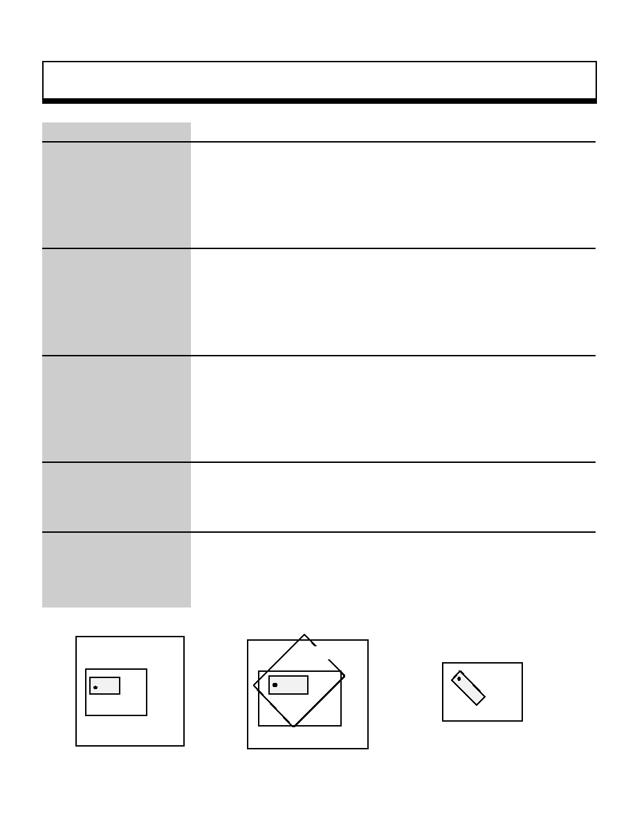
Remarks
The rotating scroll display position is determined according to the placement of the
monitor, using the rotation center coordinates as a reference point, in the
placement coordinates on the scroll map. Use the function "slLookR" to determine
the placement coordinates of the rotating scroll. For the relationship between
rotation and placement, refer to the following diagrams.
Refer to: Chapter 8, "Scrolls"
slDispCenterR
( 0 . 0 )
X
Y
Placement coordinates
Rotating scroll map
( 0 . 0 )
X
Y
Rotation center
coordinates
Monitor
Monitor
Rotating scroll map
Monitor
Z axis rotation: -90¡
Rotating scroll map
Note: The positive direction on the Z axis
for the scroll screen is towards the viewer.
_{
_Ë
Placement
_Ë
Rotation
|
Scroll Function
26
void
slKtableRA,B
Coefficient table control settings
Format
void slKtableRA(ktable_adr , mode)
void slKtableRB(ktable_adr , mode)
void *ktable_adr;
Uint16 mode;
Parameters
ktable_adr
Coefficient table address in VRAM
mode
Coefficient table control mode
Function
This function sets the coefficient table address in VRAM in a register and also
specifies how the coefficient table is to be used and its configuration.
Return Value
None
Remarks
The following parameters can be specified:
Table usage
:[K_OFF
|
K_ON
] |
Coefficient data size
:[K_2WORD
|
K_1WORD ] |
Coefficient mode
:[K_MODE0
|
K_MODE1 | K_MODE2 | K_MODE3 ] |
Line color :[K_LINECOL
] |
Unit of change
:[K_DOT
|
K_LINE
] |
Fix coefficients
: [K_FIX
] |
Note: If "fix coefficients" is specified as one of the parameters, the coefficient table
is assumed to beprepared beforehand and is not calculated in real time
.
Refer to: Chapter 8, "Scrolls
slKtableRA,B
_oe slKtableRA,B substitution values ¥_oe
|

Scroll Function
27
void
slLine1ColSet
Line single-color setting matrix setting
Format
void slLine1ColSet(adr , col)
void *adr ;
Uint16 col ;
Parameters
adr
Line color table address in VRAM
col
Color number
Function
This function sets the line color screen to a single color and sets that color.
Return Value
None
Remarks
For details on the line color screen, refer to Hardware Manual vol.2 (VDP2 User's
Manual: p.172).
Refer to: Chapter 8, "Scrolls"
slLine1ColSet
|
Scroll Function
28
void
slLineColDisp
Line color screen enable setting
Format
void slLineColDisp(flag)
Uint16 flag ;
Parameters
flag
Screen specification
Function
This function sets the screen that is to be affected by the line color when it is the
top image. Multiple screen specification is possible using the "or" operator.
Return Value
None
Remarks
The parameters that can be specified are shown in the table below.
Scroll screen to be registered
NBG0
NBG1
NBG2
NBG3
RBG0
Substitution value
NBG0ON
NBG1ON
NBG2ON
NBG3ON
RBG0ON
Note: The values in the above table are defined in "sl_def.h", provided with the system.
Refer to: Chapter 8, "Scrolls"
slLineColDisp
|

Scroll Function
29
void
slLineColTable
Line color table setting
Format
void slLineColTable(adr)
void *adr ,
Parameters
adr
Line color table address in VRAM
Function
This function sets the line color table address in VRAM in the register.
Return Value
None
Remarks
For details on the line color screen, refer to Hardware Manual vol.2 (VDP2 User's
Manual: p-173)
Refer to: Chapter 8, "Scrolls"
slLineColTable
|
Scroll Function
30
void
slLineScrollModeNbg0,1
Line scroll mode and vertical cell scroll mode setting
Format
void sLineScrollModeNbg0(mode)
void slLineScrollModeNbg1(mode)
Uint16 mode;
Parameters
mode
Line scroll mode flag
Function
This function sets the line scroll mode and vertical cell scroll mode for the scroll
screen
Return Value
None
Remarks
Line width
: [ lineSZ1 | lineSZ2 | lineSZ4 | lineSZ8 |] |
Horizontal scaling
: [ lineZoom] |
Vertical scrolling
: [ lineVScroll] |
Horizontal scrolling
: [ lineHScroll] |
Vertical cell scrolling
: [ VCellScroll]
Note: The values in the above table are defined in "sl_def.h", provided with the system.
Refer to: HARDWARE MANUAL vol. 2 (VDP2)
slLineScrollModeNbg0,1
_oe Line scroll setting flags _oe
|

Scroll Function
31
void
slLineScrollTable0,1
Line scroll table address setting
Format
void slLineScrollTable0(adr)
void slLineScrollTable1(adr)
void *adr;
Parameters
adr
Line scroll table address in VRAM
Function
This function sets the starting address for the line scroll table in VRAM where the
line scroll data was set
.
Return Value
None
Remarks
Refer to: HARDWARE MANUAL vol. 2 (VDP2)
slLineScrollTable0,1
|
Scroll Function
32
( 0 . 0 )
X
Y
Placement coordinates
Rotating scroll map
( 0 . 0 )
X
Y
Rotation center
coordinates
Monitor
Monitor
Rotating scroll map
Monitor
Z axis rotation: -90¡
Rotating scroll map
Note: The positive direction on the Z axis
for the scroll screen is towards the viewer.
_{
_Ë
Placement
_Ë
Rotation
void
slLookR
RBG placement coordinate setting
Format
void slLookR(x , y)
FIXED x ;
FIXED y ;
Parameters
x
X coordinate (scroll coordinate system) for rotating scroll placement
y
Y coordinate (scroll coordinate system) for rotating scroll placement
Function
This function sets the placement coordinates for the rotating scroll screen. The
placement coordinates indicate a point on the scroll map. The rotating scroll
screen display position is determined by placing the monitor so that the rotation
center coordinates overlay the placement coordinates.
For the parameters, substitute the XY coordinate values corresponding to the
scroll coordinate system.
Return Value
None
Remarks
The rotating scroll display position is determined according to the placement of the
monitor, using the rotation center coordinates as a reference point, in the
placement coordinates on the scroll map. Use the function "slDispCenterR" to
determine the rotation center coordinates of the rotating scroll. For the
relationship between rotation and placement, refer to the following diagrams.
Refer to: Chapter 8, "Scrolls"
slLookR
|
Scroll Function
33
void
slMakeKtable
Coefficient table creation
Format
void slMakeKtable(adr)
void*adr;
Parameters
adr
Coefficient table address in VRAM
Function
This function creates at the specified address in VRAM the coefficient table to be
used for three-dimensional rotation. ("adr" must be specified within the VDP2 RAM
area.)
Return Value
None
Remarks
Refer to: Chapter 8, "Scrolls"
slMakeKtable
|

Scroll Function
34
void
slMapNbg0,1,2,3
NBG map setting
Format
void slMapNbg0(a , b , c , d)
void slMapNbg1(a , b , c , d)
void slMapNbg2(a , b , c , d)
void slMapNbg3(a , b , c , d)
void *a , *b , *c , *c;
Parameters
a
Starting address in VRAM of pattern name data table for plane a
b
Starting address in VRAM of pattern name data table for plane b
c
Starting address in VRAM of pattern name data table for plane c
d
Starting address in VRAM of pattern name data table for plane d
Function
This function sets up the normal scroll map.
For the parameters, substitute the starting addresses in VRAM of the pattern
name data tables to be registered in the map register and the map offset register.
Return Value
None
Remarks
Refer to: Chapter 8, "Scrolls"
slMapNbg0,1,2,3
|

Scroll Function
35
void
slOverRA
RBG screen overflow processing setting (for rotation parameters A)
Format
void sllOverRA(mode)
Uint16 mode;
Parameters
mode
Uint16-type value corresponding to the screen overflow processing mode
specification
0: Outside of the display area, repeat image set in the display area
1: Outside of the display area, repeat the specified character pattern
2: Outside of the display area, leave entire area clear
3: Outside of the 512 (vertical) x 512 (horizontal) display area, leave
everything clear
Function
This function sets the screen overflow processing mode for the rotating scroll. The
screen overflow processing setting specifies how, when the rotating scroll graphics
go beyond the display area, to process the portion that exceeds the display area.
This setting is made for the rotating scroll plane size register.
Return Value
None
Remarks
When the rotating scroll is in bitmap format, mode 1 cannot be set.
Refer to: Chapter 8, "Scrolls"
slOverRA
|

Scroll Function
36
void
slOverRB
RBG screen overflow processing setting (for rotation parameters B)
Format
void slOverRB(mode)
Uint16 mode;
Parameters
mode
Uint16-type value corresponding to the screen overflow processing mode
specification
0: Outside of the display area, repeat image set in the display area
1: Outside of the display area, repeat the specified character pattern
2: Outside of the display area, leave entire area clear
3: Outside of the 512 (vertical) x 512 (horizontal) display area, leave
everything clear
Function
This function sets the screen overflow processing mode for the rotating scroll. The
screen overflow processing setting specifies how, when the rotating scroll graphics
go beyond the display area, to process the portion that exceeds the display area.
This setting is made for the rotating scroll plane size register.
Return Value
None
Remarks
When the rotating scroll is in bitmap format, mode 1 cannot be set.
Refer to: Chapter 8, "Scrolls"
slOverRB:
|

Scroll Function
37
void
slPageNbg0,1,2,3
NBG pattern name data registration
Format
void slPageNbg0(celadr , coladr , type)
void slPageNbg1(celadr , coladr , type)
void slPageNbg2(celadr , coladr , type)
void slPageNbg3(celadr , coladr , type)
void *celadr ;
void *coladr ;
UInt16 type ;
Parameters
celadr Starting address in VRAM of cell data stored in VRAM
coladr Starting address in color RAM of color data used by cells
type
Flag corresponding to the pattern name data-type specification
Function
This function sets up the normal scroll NBG0, NBG1, NBG2, and NBG3 pages.
For the parameters, specify, respectively, to the starting address (in VRAM) of the
character pattern data used on the scroll screen, the starting address (in color
RAM) for the color data used for the character patterns, and a Uint16-type value
corresponding to the pattern name data-type specification.
Return Value
None
Remarks
For the parameter "type", specify a value from the following table corresponding to
the pattern name data type.
Word length Character number bits
Substitution value
1 word
Low-order 10 bits
PNB_1WORD
Low-order 12-bits
PNB_1WORD|CN_12BIT
2 words
Low-order 16-bits
PNB_2WORD
Note: The values in the above table are defined in "sl_def.h", provided with the system.
Refer to: Chapter 8, "Scrolls"
slPageNbg0,1,2,3
|
Scroll Function
38
void
slPageRbg0
RBG pattern name data registration
Format
void slPageRbg0(celadr , coladr , type)
void *celadr ,
void *coladr ,
Uint16 type ,
Parameters
celadr Starting address in VRAM of cell data stored in VRAM
coladr Starting address in color RAM of color data used by cells
type
Flag corresponding to the pattern name data-type specification
Function
This function sets up the rotating scroll RBG0 page. For the parameters, specify,
respectively, the starting address (in VRAM) of the character pattern data used on
the scroll screen, the starting address (in color RAM) for the color data used for the
character patterns, and a Uint16-type value corresponding to the pattern name
data-type specification.
Return Value
None
Remarks
For the parameter "type", specify a value from the following table corresponding to
the pattern name data type.
Word length Character number bits
Substitution value
1 word
Low-order 10 bits
PNB_1WORD
Low-order 12-bits
PNB_1WORD|CN_12BIT
2 words
Low-order 16-bits
PNB_2WORD
Note: The values in the above table are defined in "sl_def.h", provided with the system.
Refer to: Chapter 8, "Scrolls"
slPageRbg0
|

Scroll Function
39
void
slPlaneNbg0,1,2,3
NBG plane size setting
Format
void slPlaneNbg0(type)
void slPlaneNbg1(type)
void slPlaneNbg2(type)
void slPlaneNbg3(type)
Unit16 type ;
Parameters
type
Flag corresponding to the plane size specification
Function
This function sets the plane size for normal scrolls. Refer to the table below for
the substitution values for the parameter.
Return Value
None
Remarks
When the reduction setting is set to 1/4x, do not set the plane size as 2 x 2.
This is due to the fact that the map size is different when the reduction setting is
set to 1/4x. The 1 x 1 and 2 x 1 settings can be used without any problems.
Plane size
1 (horizontal) x 1 (vertical)
2 (horizontal) x 1 (vertical)
2 (horizontal) x 2 (vertical)
Substitution value
PL_SIZE_1x1
PL_SIZE_2x1
PL_SIZE_2x2
Note: The values in the above table are defined in "sl_def.h", provided with the system.
Refer to: Chapter 8, "Scrolls"
slPlaneNbg0,1,2,3
|
Scroll Function
40
void
slPlaneRA
RBG plane size setting (for rotation parameters A)
Format
void slPlaneRA(type)
Uint16 type ;
Parameters
type
Flag corresponding to the plane size specification
Function
This function sets the plane size for rotating scrolls (using rotation parameters A).
Refer to the table below for the substitution values for the parameter.
Return Value
None
Remarks
Plane size
1 (horizontal) x 1 (vertical)
2 (horizontal) x 1 (vertical)
2 (horizontal) x 2 (vertical)
Substitution value
PL_SIZE_1x1
PL_SIZE_2x1
PL_SIZE_2x2
Note: The values in the above table are defined in "sl_def.h", provided with the system.
Refer to: Chapter 8, "Scrolls"
slPlaneRA
|

Scroll Function
41
void
slPlaneRB
RBG plane size setting (for rotation parameters B)
Format
void slPlaneRB(type)
Uint16 type ;
Parameters
type
Uint16-type value corresponding to the plane size specification
Function
This function sets the plane size for rotating scrolls (using rotation parameters B).
Refer to the table below for the substitution values for the parameter.
Return Value
None
Remarks
Plane size
1 (horizontal) x 1 (vertical)
2 (horizontal) x 1 (vertical)
2 (horizontal) x 2 (vertical)
Substitution value
PL_SIZE_1x1
PL_SIZE_2x1
PL_SIZE_2x2
Note: The values in the above table are defined in "sl_def.h", provided with the system.
Refer to: Chapter 8, "Scrolls"
slPlaneRB
|

Scroll Function
42
void
slPriorityRbg0
RBG priority setting
Format
void slPriorityRbg0(num)
Uint16 num ;
Parameters
num
Graphics priority number (8 levels, from 0 to 7)
Function
This function assigns a priority ranking to the rotating scroll.
Higher priority numbers represent a higher display priority, so the smaller the
priority number, the farther back the associated scroll screen is displayed.
If the priority number assigned is "0", the scroll is regarded to be clear and is not
displayed.
Return Value
None
Remarks
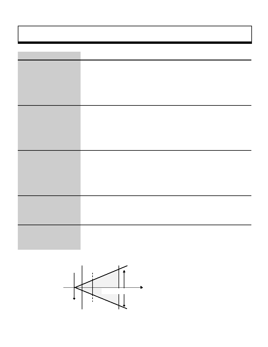
If more than one scroll or polygon has been assigned the same priority number,
their respective priority is ranked as shown below.
SPRITE>RBG0>NBG0>NBG1>NBG2>NBG3
High (forefront of screen)
Low (background of screen)
Note: Polygons are included in "sprites".
Refer to: Chapter 8, "Scrolls"
slPriorityRbg0
_oe
Priority when priority numbers are equal
_oe
|

Scroll Function
43
void
slPriorityNbg0,1,2,3
NBG priority setting
Format
void slPriorityNbg0(num)
void slPriorityNbg1(num)
void slPriorityNbg2(num)
void slPriorityNbg3(num)
Uint16 num ;
Parameters
num
Graphics priority number (8 levels, from 0 to 7)
Function
This function assigns a priority ranking to the normal scrolls NBG0, NBG1, NBG2,
and NBG3.
Higher priority numbers represent a higher display priority, so the smaller the
priority number, the farther back the associated scroll screen is displayed.
If the priority number assigned is "0", the scroll is regarded to be clear and is not
displayed.
Return Value
None
Remarks
If more than one scroll or polygon has been assigned the same priority number,
their respective priority is ranked as shown below.
SPRITE>RBG0>NBG0>NBG1>NBG2>NBG3
High (forefront of screen)
Low (background of screen)
Note: Polygons are included in "sprites".
Refer to: Chapter 8, "Scrolls"
slPriorityNbg0,1,2,3
_oe
Priority when priority numbers are equal
|

Scroll Function
44
void
slRparaInitSet
Rotation parameter table storage in VRAM
Format
void slRparaInitSet(ptr)
ROTSCROLL *ptr ;
Parameters
ptr
Starting address in VRAM where the rotation parameter table is stored
Function
This function stores in VRAM the rotation parameter table (size: 60H) used for the
rotating scroll.
Return Value
None
Remarks
When using the rotating scroll, be sure to store the rotation parameter table in
VRAM.
For details on the variable type ROTSCROLL, refer to "ROTSCROLL" in the
Structure Reference.
When setting the perspective (using the function "slPerspective", execute this
function first, before executing "slPerspective".
Refer to: Chapter 8, "Scrolls"
slRparaInitSet
|
Scroll Function
45
void
slRparaMode
Rotation parameter mode setting
Format
void slRparaMode(mode)
Uint16 mode ;
Parameters
mode
Rotation parameter mode
Function
This function specifies the rotation parameter mode. This function makes it
possible to specify how rotation parameters A and B are used.
Return Value
None
Remarks
Specify one of the following values for the rotation parameter mode.
RA: Use only rotation parameters A.
RB: Use only rotation parameters B.
K_CHANGE: Change screens according to the coefficient data of rotation
parameters A
W_CHANGE: Change screens according to the rotation parameter window.
Mode 0 Mode 1
Mode 2
Mode 3
Substitution value
RA
RB
K_CHANGE
W_CHANGE
Note:The values in the above table are defined in "sl_def.h", provided with the system
.
Refer to: Chapter 8, "Scrolls
slRparaMode
|
Scroll Function
46
void
slScrAutoDisp
Scroll registration (cycle pattern register setting)
Format
Uint16 slScrAutoDisp(ptr)
Uint32 ptr
Parameters
ptr
Scroll flag for setting the cycle pattern
Function
This function registers in the system those scrolls for which the function settings
have been completed. This function automatically sets the VRAM access
specification (in the cycle pattern register) for the scroll screen specified as the
parameter, and at the same time turns on the graphics setting for the registered
scroll.
Refer to the table below for the scroll flags to be substituted for the parameter.
To register multiple scrolls, use the "or" operator.
Return Value
If scroll registration was successful, the function returns a "0". (OK)
If scroll registration failed, the function returns a "-1" (NG).
Remarks
If scroll registration was unsuccessful, the function returns a "-1". This indicates
that the function settings and the number of screens in the scroll for which
registration was attempted was outside of the range that could be registered. In
this event, either decrease the number of screens to be registered, switch the
reduction setting from 1/4x to 1/2x, or make whatever changes need to be made,
and then attempt registration again.
Execute this function only after completing all of the scroll function settings.
This function also supports high-resoluting mode.
Scroll screen to be registered
NBG0
NBG1
NBG2
NBG3
RBG0
Substitution value
NBG0ON
NBG1ON
NBG2ON
NBG3ON
RBG0ON
Note:The values in the above table are defined in "sl_def.h", provided with the system.
Refer to: Chapter 8, "Scrolls"
slScrAutoDisp
|

Scroll Function
47
void
slScrCycleSet
Cycle pattern setting
Format
void slScrCycleSet(a , b , c , d)
Uint32 a ;
Uint32 b ;
Uint32 c ;
Uint32 d ;
Parameters
a
Bank A-0 cycle pattern
b
Bank A-1 cycle pattern
c
Bank B-0 cycle pattern
d
Bank B-1 cycle pattern
Function
This function sets the cycle pattern for each bank. When each bank is partitioned,
cycle patterns can be set for a and b and for c and d. If the banks are not
partitioned, cycle patterns can be set for a and c. For details on the settings, refer
to pp. 31 and beyond in the HARDWARE MANUAL vol. 2, VDP2 User's Manual.
Return Value
None
Remarks
If the function "slScrAutoDisp" is used, "slScrCycleSet" can be used to
automatically set the cycle pattern for displaying the scroll screen specified by
"slScrAutoDisp".
slScrCycleSet (0xffffffff , 0x66554444 , 0xffffffff , 0x0012ffff);
A0 access setting
A1 access setting
B0 access setting
B1 access setting
Refer to: HARDWARE MANUAL vol. 2 (VDP2)
slScrCycleSet
|
Scroll Function
48
void
slScrDisp
Display setting for scroll specified as parameter
Format
void slScrDisp(mode)
Uint32 mode;
Parameters
mode
Display flag for scroll screen to be displayed
Function
This function makes the display setting for the scroll screen specified as the
parameter.
Refer to the table below for the parameter substitution values.
To simultaneously set multiple scrolls for display, link the parameters with the "or"
operator ("|").
Return Value
None
Remarks
The display setting determines which of the registered scrolls will actually undergo
drawing processing. Only those scroll screens for which the display setting is "ON"
will actually be drawn on the monitor by the drawing start declaration.
Scrolls that were registered by using the function "slAutoDisp" have their display
setting set to "ON" at the time of registration.
NBG0
NBG1
NBG2
NBG3
RBG0
ON
OFF
ON
OFF
ON
OFF
ON
OFF
ON
OFF
Substitution
value
NBG0ON
NBG0OFF
NBG1ON
NBG1OFF
NBG2ON
NBG2OFF
NBG3ON
NBG3OFF
RBG0ON
RBG0OFF
Note:
The values in the above table are defined in "sl_def.h", provided with the system.
ON: Draw scroll screen.
OFF: Do not draw scroll screen.
Refer to: Chapter 8, "Scrolls
slScrDisp
|
Scroll Function
49
void
slScrLineWindow0
Line window table0 setup
Format
void slScrLineWindow0(adr)
void *adr ;
Parameters
adr
Line window data address in VRAM
Function
This function sets the address in VRAM of line window data table 0.
Return Value
None
Remarks
To enable a window, set the high-order bit to "1". To disable a window, pass the
NULL value.
Ex.: address = 0x25e3f000 (when constant is specified)
Use window:
slLineWindow0((void*)(0x25e3f000@SPECIAL SYMBOL@0x80000000));
Do not use window:
slLineWindow0((void*)NULL);
address = 0x25e3f000 (when constant is specified)
Use window:
Sint16 *1ptr ;
1pts = (Sint16*) 0x25e3f000 ;
slLine Window0 ((void*)(1pts *@0x40000000)) ;
Do not use window:
slLine Window0 ((void*)NULL) ; 1pts is Sint16 (2-byte variable) pointer
Refer to: HARDWARE MANUAL vol. 2 (VDP2)
slScrLineWindow0
|

Scroll Function
50
void
slScrMatConv
Convert current matrix to scroll format matrix
Format
void slScrMatConv(void)
Parameters
None
Function
This function converts the current matrix into a scroll-format matrix. If this function
is used, the current matrix is overwritten.
Return Value
None
Remarks
To save the current matrix, execute the matrix function "slPushMatrix" before
executing this function to rest the matrixs.
An example of how to save the current matrix is shown below.
slPushMatrix();
/* save current matrix */
{
slRotX(DegtoAng(90));
/* change sides to bottom */
slScrMatConv()
/* matrix conversion */
slScrMatSet();
/* rotation parameter setting */
}
slpopMatrix();
/* execute current matrix */
Refer to: HARDWARE MANUAL vol. 2 (VDP2)
slScrMatConv
_oe
Saving the current matrix
_oe
|

Scroll Function
51
void
slScrMatSet
Matrix setting
Format
void slScrMatSet()
Parameters
None
Function
This function uses the current matrix to set the RBG0 rotation parameters.
Return Value
None
Remarks
Also supports high-resolution mode.
Refer to: Chapter 8, "Scrolls"
slScrMatSet
|
Scroll Function
52
void
slScrMosaicOn
Mosaic processing specification screen
Format
void slScrMosaicOn(screen)
Uint16 screen ;
Parameters
screen Flag for scroll on which mosaic processing is to be performed
Function
This function sets the scroll screen on which mosaic processing is to be performed.
Multiple scroll screens can be specified simultaneously by linking multiple
parameters together with the "or" operator.
Return Value
None
Remarks
For the parameter "screen", substitute the value from the table below
corresponding to the scroll screen being specified.
Scroll screen being specified
NBG0
NBG1
NBG2
NBG3
RBG0
Substitution value
NBG0ON
NBG1ON
NBG2ON
NBG3ON
RBG0ON
Note:The values in the above table are defined in "sl_def.h", provided with the system
.
Refer to: HARDWARE MANUAL vol. 2 (VDP2)
slScrMosaicOn
|

Scroll Function
53
void
slScrMosSize
Horizontal and vertical specification of mosaic processing size
Format
void slScrMosSize(Hsize , Vsize)
Uint16 Hsize ;
Uint16 Vsize ;
Parameters
Hsize
Horizontal size for mosaic processing
Vsize
Vertical size for mosaic processing
Function
This function specifies the horizontal and vertical sizes, in dots (range: 1 to 16), for
mosaic processing.
In non-interlaced mode, specify 1 to 16 dots in both the vertical and horizontal
directions.
In interlaced mode, specify 2 to 32 dots in the vertical direction and 1 to 16 dots in
the horizontal direction.
When mosaic processing is performed on the rotating scroll, it is only performed in
the horizontal direction.
Return Value
None
Remarks
Refer to: HARDWARE MANUAL vol. 2 (VDP2)
slScrMosSize
|
Scroll Function
54
void
slScrPosNbg0,1,2,3
NBG screen display position setting
Format
void slScrPosNbg0(x , y)
void slScrPosNbg1(x , y)
void slScrPosNbg2(x , y)
void slScrPosNbg3(x , y)
FIXED x ;
FIXED y ;
Parameters
x
X coordinate (scroll coordinate system) for normal scroll placement
y
Y coordinate (scroll coordinate system) for normal scroll placement
Function
This function positions the respective normal scroll screens NBG0, NBG1, NBG2,
and NBG3. For the parameters, specify the XY scroll coordinate values that
indicate the display position.
Return Value
None
Remarks
The concept behind the display position specification for normal scroll screens is
illustrated below. (The monitor is positioned on the scroll map.)
Refer to: Chapter 8, "Scrolls"
slScrPosNbg0,1,2,3
Move position to right
X
Y
Monitor
Nomal scroll map
a) Initial state
X
Y
Monitor
b) Move to right
_Ë
:
The scroll display position is processed through the scroll screen
coordinate system.
:
This coordinate system designates the upper-left corner of each
scroll or map as the origin.
:
The scroll display position is specified by indicating where in the
coordinate system the monitor should be positioned.
(The representative points the upper-left corner of the monitor.)
:
As a result, if the scroll display position coordinates are moved in
the positive direction along the X axis (to the right), the monitor
moves to the right on the scroll map, giving the appearance that
the scroll is moving to the left.
|

Scroll Function
55
void
slScrTransparent
Transparent enable display setting
Format
void slScrTransparent(flag)
Uint16 flag ;
Parameters
flag
Flag specifying the transparent display setting
Function
This function specifies the handling of the transparent color for each scroll.
The specification can be made for multiple scroll screens simultaneously by linking
the parameters with the "or" operator.
Return Value
None
Remarks
The parameters shown below can be specified for "flag".
For scroll screens specified by the parameter, the No. 0 character is drawn
according to the data for that character; for scroll screens not specified by the
parameter, the No. 0 character is drawn on the screen as a transparent character.
Scroll screen being specified
NBG0
NBG1
NBG2
NBG3
RBG0
Substitution
value
NBG0ON
NBG1ON
NBG2ON
NBG3ON
RBG0ON
Note:The values in the above table are defined in "sl_def.h", provided with the system
.
Refer to: Chapter 8, "Scrolls"
slScrTransparent
|
Scroll Function
56
void
slScrWindow0
Scroll rectangular window 0setting
Format
void slScrWindow0(Left , Top , Right , Bottom)
Uint16 Left ;
Uint16 Top ;
Uint16 Right ;
Uint16 Bottom ;
Parameters
Left
X coordinate of upper left corner of window
Top
Y coordinate of upper left corner of window
Right
X coordinate of lower right corner of window
Bottom Y coordinate of lower right corner of window
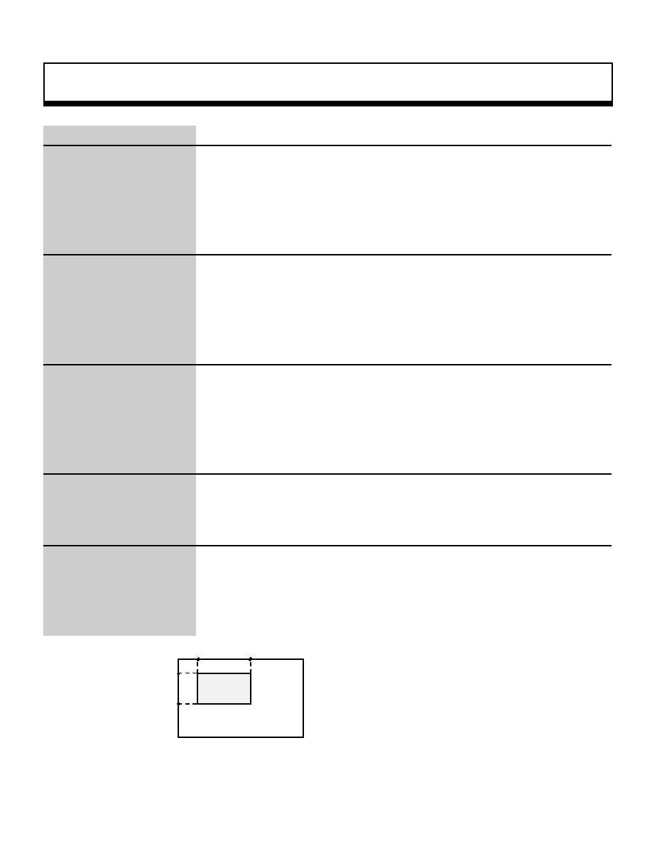
Function
This function specifies the scroll window 0 area. The rectangular window area is
defined by specifying the upper left coordinates (Left, Top) and the lower right
coordinates (Right, Bottom).
Return Value
None
Remarks
Refer to: HARDWARE MANUAL vol. 2 (VDP2)
slScrWindow0
( 0 . 0 )
Window
top
bottom
left
right
Monitor
( 319, 223 )
Note: "left", "top", "right" and "bottom" indicate the XY coordinate values for the monitor
|
Scroll Function
57
void
slScrWindowModeNbg0,1,2,3
NBG window usage mode setting
Format
void slScrWindowModeNbg0(mode)
void slScrWindowModeNbg1(mode)
void slScrWindowModeNbg2(mode)
void slScrWindowModeNbg3(mode)
Uint16 mode ;
Parameters
mode
Window usage mode flag
Function
This function sets the NBG0 to 3 window usage mode.
Return Value
None
Remarks
For the parameters, substitute the values shown in the illustration below. Multiple
parameters can be specified simultaneously by linking each group of parameters
with the "or" operator.
In the parameters shown below, "*_IN" displays the graphic element inside the
window, and "*_OUT" displays the graphic element outside the window.
Window 0
:[Use_win0 ] |
Window 1
:[Use_win1 ] |
Sprite window
:[Use_spw ] |
Window condition
:[win_OR | win_AND ]|
Display area setting (Win0)
:[win0_IN
| win0_OUT ] |
Display area setting (Win1)
:[win1_IN
| win1_OUT ] |
Display area setting (SpWin)
:[spw_IN | spw_OUT ] |
Note: The values in the above table are defined in "sl_def.h", provided with the system.
Refer to: HARDWARE MANUAL vol. 2 (VDP2)
slScrWindowModeNBG0,1,2,3
_oe
slScrWindowMode substitution values
_oe
|
Scroll Function
58
void
slShadowOn
Shadow function setting
Format
void slShadowOn(scrn)
Uint16 scn;
Parameters
scrn
Flag corresponding to the scroll screen for which the shadow function is
set
Function
This function sets the scroll screen on which the shadow function is used.
Multiple scroll screens can be set simultaneously by linking multiple parameters
together with the "or" operator.
Return Value
None
Remarks
Refer to the table below for the scroll flags that are substituted for the parameter.
When setting multiple scroll screens, use the "or" operator.
Scroll screen being specified
NBG0
NBG1
NBG2
NBG3
RBG0
BACK
Substitution value
NBG0ON
NBG1ON
NBG2ON
NBG3ON
RBG0ON
BACKON
Note: The values in the above table are defined in "sl_def.h", provided with the system.
Refer to: HARDWARE MANUAL vol. 2 (VDP2)
slShadowOn
|

Scroll Function
59
void
slTVOff
Drawing end declaration
Format
void slTVOff()
Parameters
None
Function
This function turns off scroll drawing processing in the monitor.
Return Value
None
Remarks
To re-initiate drawing in the monitor, execute the drawing start declaration
"slTVOn".
Refer to: Chapter 8, "Scrolls'
slTVOff
|

Scroll Function
60
void
slTVOn
Drawing start declaration
Format
void slTVOn()
Parameters
None
Function
This function starts drawing in the scroll screen monitor.
Return Value
None
Remarks
To stop drawing in the monitor, execute the drawing end declaration "slTVOff".
Refer to: Chapter 8, "Scrolls"
slTVOn
|
Scroll Function
61
void
slZoomModeNbg0,1
NBG expansion/reduction mode determination
Format
void slZoomModeNbg0(mode)
void slZoomModeNbg1(mode)
Uint16 mode ;
Parameters
mode
Flag corresponding to the zoom mode specification
Function
This function sets the expansion/reduction mode in the reduction enable register
for NBG0 and NBG1, which are the only normal scrolls that permit
expansion/reduction
Return Value
None
Remarks
Depending on the reduction setting, the range for expansion/reduction changes
as follows:
Reduction setting 1/1x: (1/1x to 256x)
Reduction setting 1/2x: (1/2x to 256x)
Reduction setting 1/4x: (1/4x to 256x)
Reduction setting
1x
1/2x
1/4x
Substitution value
ZOOM_1
ZOOM_HALF
ZOOM_QUATER
Note: The values in the above table are defined in "sl_def.h", provided with the system.
Refer to: Chapter 8, "Scrolls"
slZoomModeNbg0,1
|
Scroll Function
62
void
slZoomNbg0,1
NBG expansion/reduction
Format
void slZoomNbg0(x , y)
void slZoomNbg1(x , y)
FIXED x ,
FIXED y ,
Parameters
x
Reciprocal of expansion/reduction ratio in direction of X axis for normal
scroll
y
Reciprocal of expansion/reduction ratio in direction of Y axis for normal
scroll
Function
This function sets the expansion/reduction ratio for NBG0 and NBG1, the only
normal scrolls that permit expansion/reduction.
For the parameters, substitute the reciprocals of the scale values in the direction
of the X and Y axes, respectively. For example, to enlarge the figure by 2.0x in
the direction of the X axis, substitute 1/2 for the parameter "x".
Return Value
None
Remarks
The range over which expansion/reduction is possible differs according to the
reduction setting for the scroll screen being expanded/reduced.
The reduction setting is made by the function "slZoomModeNbg0,1".
For the expansion/reduction range according to the reduction setting, refer to the
table below.
Reduction setting
1x
1/2x
1/4x
Expansion/reduction range
1x to 256x
1/2x to 256x 1/4x to 256x
Refer to: Chapter 8, "Scrolls"
slZoomNbg0,1
|

Scroll Function
63
void
slZoomR
RBG expansion/reduction
Format
void slZoomR(x , y)
FIXED x ,
FIXED y ,
Parameters
x
Reciprocal of expansion/reduction ratio in direction of X axis for normal
scroll
y
Reciprocal of expansion/reduction ratio in direction of Y axis for normal
scroll
Function
This function sets the expansion/reduction ratio for the rotating scroll, and saves
the setting in the current rotation parameters.
For the parameters, substitute the reciprocals of the scale values in the direction
of the X and Y axes, respectively. For example, to enlarge the figure by 2.0x in
the direction of the X axis, substitute 1/2 for the parameter "x".
Return Value
None
Remarks
Unlike with normal scrolls, the enlargement/reduction ratio can be set to any
desired ratio for the rotating scroll.
Refer to: Chapter 8, "Scrolls"
slZoomR
|
Scroll Function
64
void
slZrotR
RBG Z axis rotation
Format
void slZrotR(angz)
ANGLE angz ;
Parameters
angz
Rotation angle of rotating scroll versus Z axis
Function
This function rotates the rotating scroll versus the Z axis.
The Z axis (the positive direction is towards the viewer) is used as the rotation axis,
and rotation on the positive direction is towards the right (clockwise).
Return Value
None
Remarks
The coordinates specified by the function "slDispCenterR" are the center of
rotation for the rotating scroll. (The monitor rotates versus the scroll map.)
Refer to: Chapter 8, "Scrolls"
slZrotR
( 0 . 0 )
( 0 . 0 )
Monitor
Monitor
Monitor
Screen scroll map
_Ë
Rotation
_Ë
Display
Z axis rotation: -45¡
Z axis rotation: -45¡
Rotation scroll map
Rotating scroll rotation is achieved by rotating
the monitor versus the scroll map.
|

SpriteFunction
65
void
slDispSprit
Sprite display with specification of position, scale, and rotation angle
Format
void slDispSprite(pos , atrb , Zrot)
FIXED *pos ;
SPR_ATTR *atrb ;
ANGLE Zrot;
Parameters
pos[XYZ]
XYZ coordinate values for sprite placement, and scale value
atrb
Starting address of area where sprite characteristics are stored
Zrot
Z axis rotation angle
Function
This function displays a sprite, specifying the position, scale, and rotation angle.
Just as in the function "slPutPolygon", sorting is performed according to the Z
value. The display of a sprite set by this function is completely unaffected by
the current matrix.
Return Value
None
Remarks
If a negative value is input for the scale, calculate the scale according to the Z
position, multiply it by the complement of the scale, and use the result as the
display scale.
For example, if -2.0 is specified for the scale, and the sprite is in a position (Z
position) where it should be displayed at 0.5x, the sprite is displayed at 1.0x.
The display of the sprite is not affected by the current matrix.
Refer to: Chapter 9, "Controller Input"
slDispSprite
|

SpriteFunction
66
void
slPutSprite
Sprite display with perspective transformation effects
Format
void slPutSprite(pos , atrb , Zrot)
FIXED *pos ;
SPR_ATTR *atrb ;
ANGLE Zrot ;
Parameters
pos[XYZ]
XYZ coordinate values for sprite placement, and scale value
atrb
Starting address of area where sprite characteristics are stored
Zrot
Z axis rotation angle
Function
This function calculates the position using the current matrix and displays the
sprite after applying scaling effects in accordance with perspective
transformation.
As with the function "slDispSprite", scaling is performed according to the
specified scale value. If a negative value is specified, the absolute value is
used.
Return Value
None
Remarks
Refer to: Chapter 9, "Controller Input"
slPutSprite
|

SpriteFunction
67
void
slSetSprite
Sprite data setting
Format
void slSetSprite(parms , Zpos)
SPRITE *parms ;
FIXED Zpos ;
Parameters
parms Starting address of area where sprite data is stored
Zpos
Z coordinate position
Function
This function sets the sprite
control command data to be transferred to the
hardware in the transfer list.
This function is used to set altered sprites that cannot be created with the library
functions or to set up a window that affects specific sprites only.
Return Value
None
Remarks
For details on the effects of execution of the function "slSetSprite", refer to p.
118 and beyond in HARDWARE MANUAL vol. 2, VDP1 User's Manual.
Refer to: Chapter 9, "Controller Input"
slSetSprite
|

SpriteFunction
68
void
slSpriteType
Sprite data type specification
Format
void slSpriteType(type)
Uint16 type ;
Parameters
type
Sprite type (0 to 15)
Function
This function specifies the sprite data type.
Return Value
None
Remarks
Types 0 to 7 are for low resolution (320 or 352) and types 8 to 15 are for high
resolution (640 or 704); the data widths are 16 bits and 8 bits, respectively.
Refer to: HARDWARE MANUAL vol. 2 (VDP2)
slSpriteType
|

Text Display Function
69
void
slDispHex
Hexadecimal screen display
Format
void slDispHex(val , dspadd)
Uint32 val ,
void *dspadd ,
Parameters
val
Value to be displayed
dspadd Text display address ("slLocate" return value)
Function
This function displays the specified variable in eight hexadecimal digits. The
function "slDispHex" displays zeroes in the high-order digits. (Ex.: 00001234) If
you do not wish to display zeroes in the high-order digits, use the function
"slPrintHex" (which will replace the zeroes with spaces; ex.: 1234).
Return Value
None
Remarks
The text and numeric value display function group set and register the
normal
scroll NBG0 and the ASCII cells during system initialization and use these ASCII
cells to display numeric values If, for some reason, this default data is
overwritten, text and numeric values will not be displayed properly.
Refer to: Chapter 8, "Scrolls"
slDispHex
|
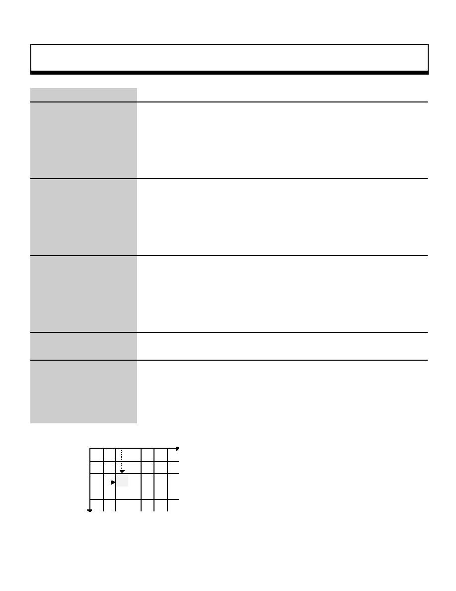
Text Display Function
70
void
slLocate
Display position calculation (parameters: cell specification)
Format
void *slLocate(xpos , ypos)
Uint16 xpos ,
Uint16 ypos ,
Parameters
xpos
X coordinate of text display position (range: 0 to 63 cells)
ypos
Y coordinate of text display position (range: 0 to 63 cells)
Function
This function returns the address value for text display.
The parameters indicate the XY coordinate position (in cell units) of the display
on the screen. One cell consists of 8 x 8 dots, and a normal scroll screen
consists of 64 x 64 cells.
Return Value
Text display address value
Remarks
Example of how to use the function "slLocate"
Uint16x=y=2;
slPrint("ABC",slLocate (x,y));
_@_@_@
0
1
2
3
4
5
0
1
2
A
B
C
3
Y
Refer to: Chapter 8, "Scrolls"
slLocate
Uint16x=y=2 ;
slPrint("ABC" ,slLocate(3,2));
X
¥ The grid in the diagram at left indicates individual cells.
¥ One cell consists of 8 x 8 dots, and the upper-left corner is the origin.
|

Text Display Function
71
void
slPrint
Character string screen display
Format
void slPrint(string , dspadd)
char *string ,
void *dspadd ,
Parameters
string
Text string to be displayed
dspadd Text display address ("slLocate" return value)
Function
This function displays the character string specified as a parameter on the
screen.
Return Value
None
Remarks
Refer to: Chapter 8, "Scrolls"
slPrint
|

Text Display Function
72
void
slPrintFX
Fixed-point decimal screen display
Format
void slPrintFX(val , dspadd)
FIXED val ,
void *dspadd ,
Parameters
val
FIXED-type numeric value to be displayed
dspadd Text display address ("slLocate" return value
Function
This function displays the FIXED-type value specified as a parameter on the
screen. Zeroes in the high-order digits in the integer portion of the value and
zeroes in the low-order digits in the decimal portion of the value are displayed as
spaces. The integer portion and the decimal portion are both displayed as five-
digit decimal numbers. If the value is negative, a "-" is displayed.
Return Value
None
Remarks
Ex.:
val = 0x00108000 _¨
16.5
val = 0xffedc000 _¨
-19.25
Refer to: Chapter 8, "Scrolls"
slPrintFX
|

Text Display Function
73
void
slPrintHex
Hexadecimal screen display (zeroes in high-order digits are not displayed)
Format
void slPrintHex(val , dspadd)
Uint32 val ,
void *dspadd ,
Parameters
val
Value to be displayed
dspadd Text display address ("slLocate" return value)
Function
This function displays the specified variable as an eight-digit hexadecimal
number on the screen. The function "slPrintHex" does not display zeroes in the
high-order digits. Zeroes in high-order digits are replaced with spaces. (Ex.:
1234) To display zeroes in the high-order digits, use the function "slDispHex".
(Ex.: 00001234)
Return Value
None
Remarks
Refer to: Chapter 8, "Scrolls"
slPrintHex
|

Text Display Function
74
void
slPrintMatrix
Matrix screen display
Format
void slPrintMatrix(mtrx , dspadd)
MATRIX mtrx ,
void *dspadd ,
Parameters
mtrx
MATRIX-type variable to be displayed
dspadd Text display address ("slLocate" return value)
Function
This function displays the specified matrix as a 4-row x 3-column matrix on the
screen.
Return Value
None
Remarks
Refer to: Chapter 8, "Scrolls"
slPrintMatrix
|

Matrix Function
75
void
slGetMatrix
Hexadecimal screen display
Format
void slGetMatrix(mtpr)
MATRIXmtpr ;
Parameters
mtptr
Starting address of MATRIX-type variable to be copied (input)
Function
This function copies the current matrix to the specified matrix.
Return Value
None
Remarks
Example of usage:
MATRIXmat ;
slGetMatrix(mat) ;
slPrintMatrix(mat, slLocate(3,4)) ;
Refer to: Chapter 5, ""Matrices"
slGetMatrix
|
Matrix Function
76
void
slInitMatrix
Matrix variable and buffer initialization
Format
void *slInitMatrix()
Parameters
None
Function
This function initializes the variables and buffers used in matrix operations, and
prepares the environment matrix (unit matrix) for the current matrix.
Return Value
None
Remarks
Refer to: Chapter 5, "Matrices"
slInitMatrix
|

Matrix Function
77
void
slInversMatrix
Current matrix inversion transformation
Format
void slInversMatrix()
Parameters
None
Function
This function inverts the current matrix
Return Value
None
Remarks
Refer to:
slInversMatrix
|

Matrix Function
78
void
slLoadMatrix
Copy specified matrix to current matrix
Format
void slIoadMatrix(mtptr)
MATRIX mtptr:
Parameters
mtptr
Starting address of the MATRIX-type variable to be copied (output)
Function
This function copies the specified matrix to the current matrix.
Return Value
None
Remarks
Refer to: Chapter 5, "Matrices"
slLoadMatrix
|
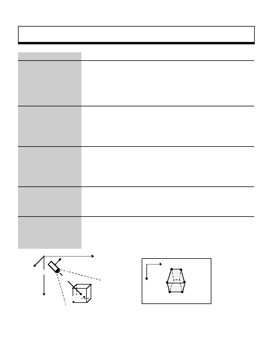
Matrix Function
79
X
Y
Projection surface
void
slLookAt
Multiply line of sight matrix by current matrix
Format
void slLookAt(camera, target, angz)
FIXED *camera;
FIXED *target;
ANGLE angz;
Parameters
camera[XYZ] XYZ coordinates indicating camera position
target[XYZ]
XYZ coordinates indicating target position
angz
Camera angle
Function
This function multiplies current matrix and the matrix (line of sight matrix) for
viewing the target from the specified camera position at the specified angle.
Return Value
None
Remarks
When a line of sight parallel with the Y axis is selected, vectors on the XZ plane
become small (the rotation around the Y axis cannot be determined) and graphics
may not be drawn properly; therefore, adjust the values so that the line of sight is
not parallel with the Y axis when using this function. The diagrams below illustrate
the line of sight concept.
Refer to: Chapter 6, "The Camera"
slLookAt
Angle: Angle of twist versus the line of sight
Line of sight
Object
a) Conceptual model of camera
Target
Viewpoint
Y
X
0
Z
b) Image seen by camera
|

Matrix Function
80
void
slMultiMatrix
Multiply specified matrix by current matrix
Format
void slMultiMatrix(mtptr)
MATRIX mtptr :
Parameters
mtptr
Starting address of MATRIX-type variable being multiplied (output)
Function
This function multiplies the specified matrix by the current matrix and makes the
result the new current matrix.
Return Value
None
Remarks
In the SGL, matrices are stored in memory as 4-row x 3-column matrices.
However, when performing mathematical operations on matrices such as with this
function, due to the fundamental concepts of matrix operations, the matrices are
expanded internally into 4-row x 4-column matrices (as shown below) when the
operations are executed.
A01 A00 A02
0
B01 B00 B02
0
A11 A10 A12
0
B11 B10 B12
0
A21 A20 A22
0
B21 B20 B22
0
A31 A30 A32
1
B31 B30 B32
1
C01 C00 C02
0
C01 C00 C02
C11 C10 C12
0
C11 C10 C12
C21 C20 C22
0
C21 C20 C22
C31 C30 C32
1
C31 C30 C32
Refer to: Chapter 5, "Matrices"
slMultiMatrix
A =
A*B = C =
B =
a) Matrices expanded into 4-row X 4-column matrices
Expanded matrix column
Convert to 4-row x
3-column matrix
_
Ë
b) Multiplication of expanded matrices and final result
|
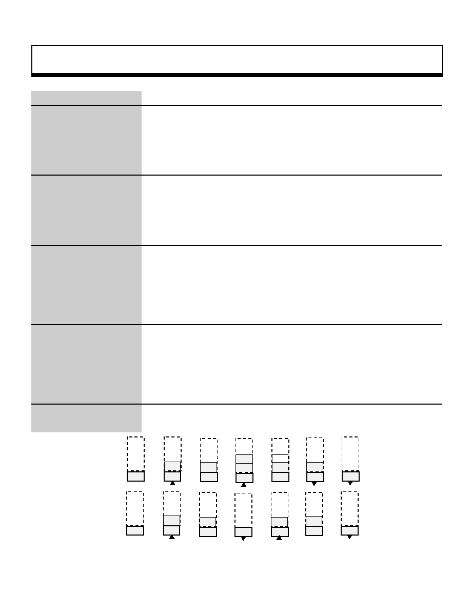
Matrix Function
81
Bool
slPopMatrix
Calling a temporarily stored matrix
Format
Bool slPopMatrix()
Parameters
None
Function
This function sends the matrix buffer pointer back one step.
Return Value
If no matrices are nested, the function returns the FALSE value.
Remarks
The following diagram illustrates the stack model.
Refer to: Chapter 5, "Matrices"
slPopMatrix
M1
M1
M1
M1
M2
M1
M2
M2
M1
M2
M4
M1
M2
M1
_Ë
_Ë
_Ë
_Ë
_Ë
_Ë
slPush
slPush
slTrance
slTrance
slPop
slPop
M1
M1
M1
M1
M2
M1
M1
M1
M1
M3
M1
_Ë
_Ë
_Ë
_Ë
_Ë
_Ë
slPush
slPush
slTrance
slTrance
slPop
slPop
|
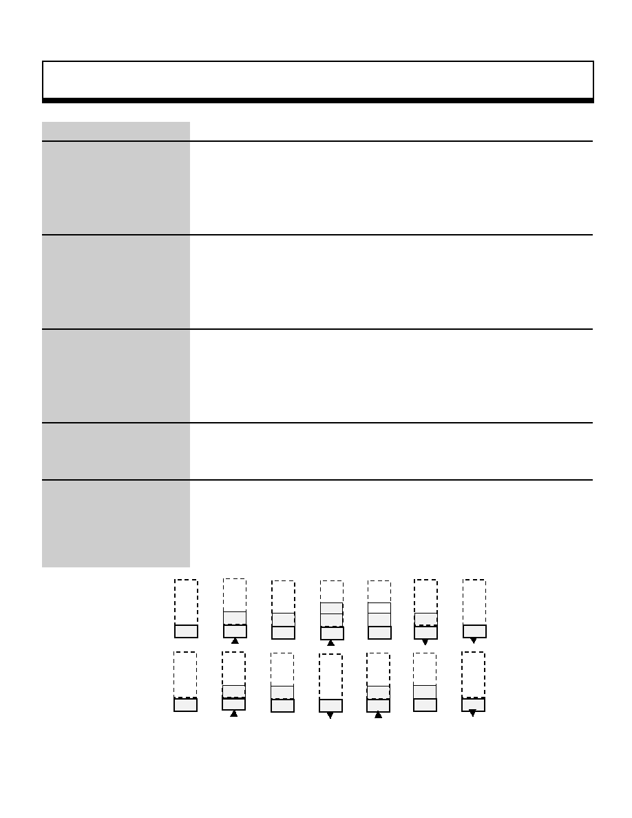
Matrix Function
82
Bool
slPushMatrix
Temporary storage of matrix (up to 20 matrices can be nested
Format
Bool slPopMatrix()
Parameters
None
Function
This function advances the matrix buffer pointer, copies the previous current matrix
to the stack, and makes that the new current matrix.
Return Value
If pointer allocation failed, the function returns the FALSE value.
Remarks
Up to 20 matrices can be nested in the buffer.
If an attempt is made to nest more than 20 matrices in the matrix buffer, the
function returns the FALSE value.
The following diagram illustrates the stack model.
Refer to: Chapter 5, "Matrices"
slPushMatrix
M1
M1
M1
M1
M2
M1
M2
M2
M1
M2
M4
M1
M2
M1
_Ë
_Ë
_Ë
_Ë
_Ë
_Ë
slPush
slPush
slTrance
slTrance
slPop
slPop
M1
M1
M1
M1
M2
M1
M1
M1
M1
M3
M1
_Ë
_Ë
_Ë
_Ë
_Ë
_Ë
slPush
slPush
slTrance
slTrance
slPop
slPop
|

Matrix Function
83
Bool
slPushUnitMatrix
Advance pointer and copy unit matrix to current matrix
Format
Bool slPushUnitMatrix()
Parameters
None
Function
This function advances the matrix buffer pointer and then sets a unit matrix in the
current matrix.
Return Value
If pointer allocation failed, the function returns the FALSE value.
Remarks
Up to 20 matrices can be nested in the buffer.
If an attempt is made to nest more than 20 matrices in the matrix buffer, the
function returns the FALSE value.
Refer to: Chapter 5, "Matrices"
slPushUnitMatrix
|
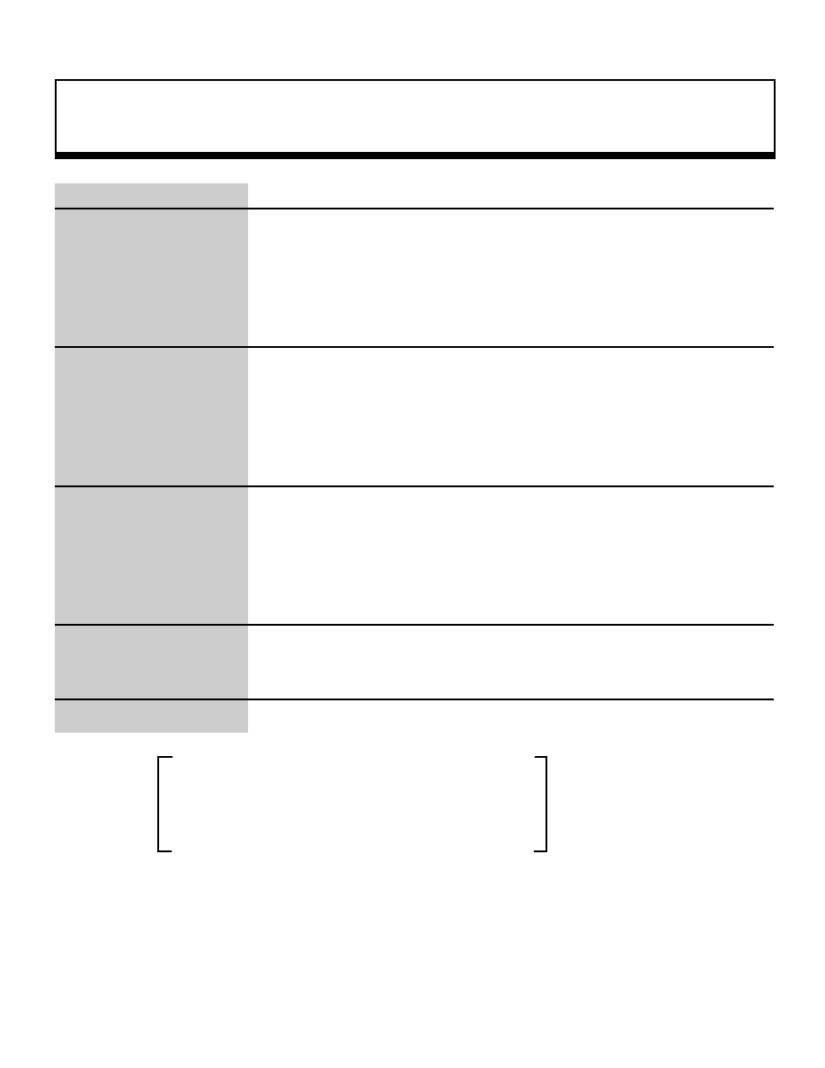
Matrix Function
84
void
slRotAX
Rotation around any axis that passes through origin alling a temporarily stored matrix
Format
void slRoaAX(vctx , vcty , vctz , anga)
FIXED vctx ;
FIXED vcty ;
FIXED vctz ;
ANGLE anga ;
Parameters
vctx X component of rotation axis vector
vcty Y component of rotation axis vector
vctz Z component of rotation axis vector
anga
Rotation angle
Function
This function adds rotation around any axis that passes through the origin. The
rotation axis vector that determines the axis of rotation must be specified by a unit
vector. The rotation matrix is expressed as shown below.
Return Value
None
Remarks
The rotation matrix used for adding rotation around any vector is shown below.
NxNx(1-C)+,b
NxNy(1-C)+NzS
NxNz(1-C)-NyS
Rax =
NyNx(1-C)-NzS
NyNy(1-C
NyNz(1-C)+NxS
NzNx(1-C)+NyS NzNy(1-C+NxS
NzNz(1-C)+C
0.0
0.0
0.0
Note:
Nx, Ny, and Nz are the X, Y, and Z components of the rotation axis vector.
S and C are the sine and cosine ofthe angle "anga".
Refer to: Chapter 4, "Coordinate Transformation
slRotAX
|
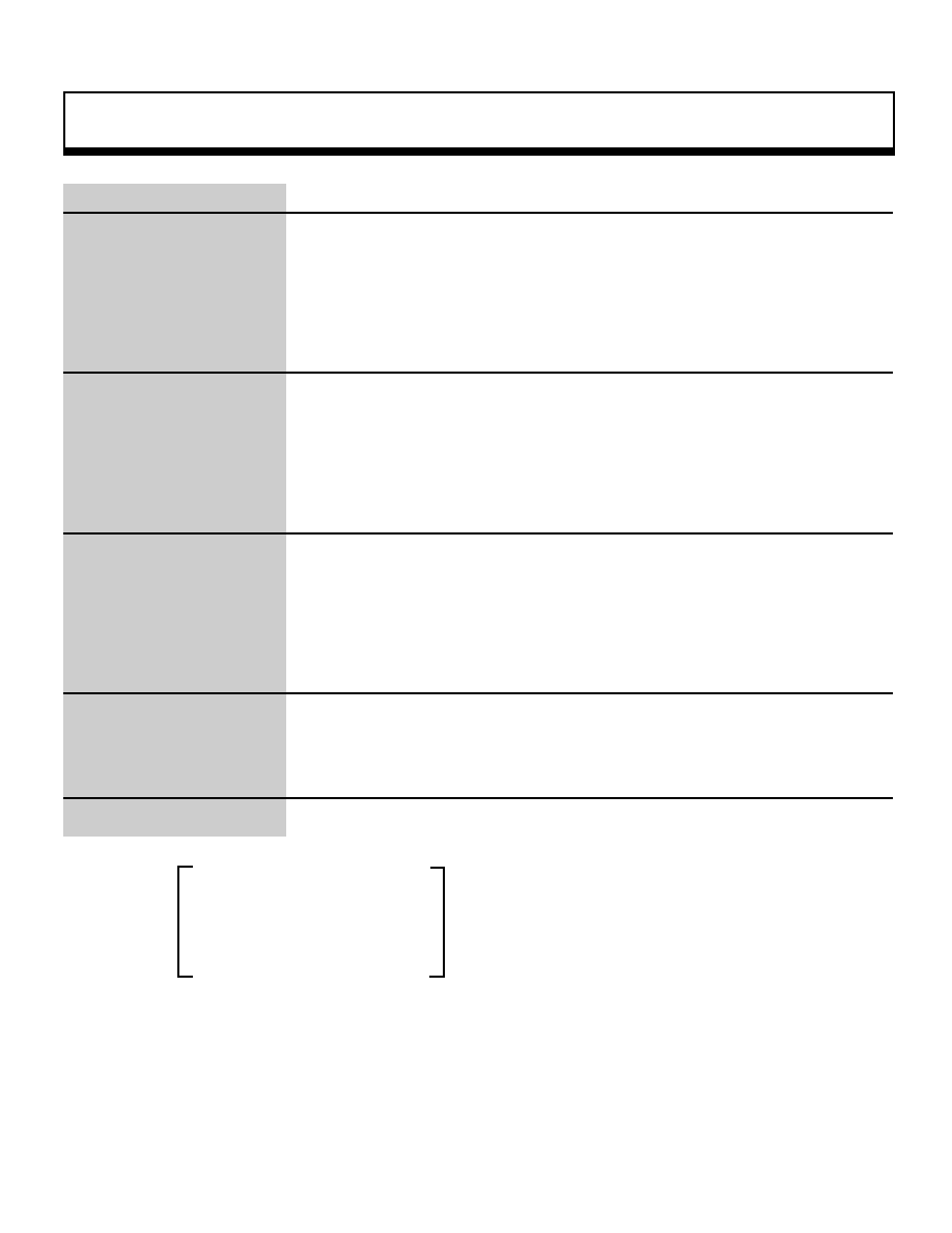
Matrix Function
85
void
slRotX
Adding rotation around X axis to current matrix
Format
void slRotX(angx)
ANGLEangx;
Parameters
angx
Angle of rotation around X axis
Function
This function multiplies an X axis rotation matrix with the current matrix. The
rotation matrix is expressed below.
Return Value
None
Remarks
1.0
0.0
0.0
Rx
=
0.0
cosÆ
sinÆ
0.0
-sinÆ
cosÆ
0.0
0.0
0.0
a) Rotation matrix for adding rotation around the X axis
Refer to: Chapter 4, "Coordinate Transformation
slRotX
|

Matrix Function
86
void
slRotXSC
Adding X axis rotation with sine and cosine specified
Format
void slRotXSC(sn , cs)
FIXED sn ;
FIXED cs ;
Parameters
sn
Angle of rotation versus X axis after sine transformation
cs
Angle of rotation versus X axis after cosine transformation
Function
This function specifies the sine and cosine and multiplies the values with the X-
axis rotation matrix. The rotation matrix is expressed as shown below.
Return Value
None
Remarks
1.0
0.0
0.0
Rxsc
=
0.0
cs
s n
0.0
-sn
cs
0.0
0.0
0.0
Note: "cs" and "sn" are the parameter substitution values
Refer to: Chapter 4, "Coordinate Transformation
slRotXSC
|
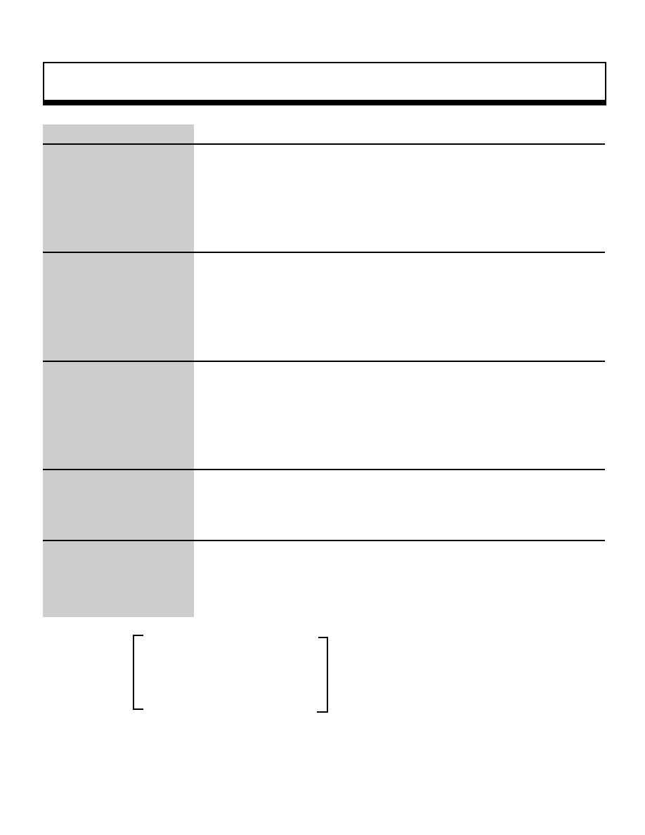
Matrix Function
87
void
slRotY
Adding rotation around Y axis to current matrix
Format
void slRotY(angy)
ANGLEangy ;
Parameters
angy
Angle of rotation around Y axis
Function
This function multiplies a Y axis rotation matrix with the current matrix. The rotation
matrix is expressed below.
Return Value
None
Remarks
cosÆ
.0.0
-sinÆ
Ry
=
0.0
1.0
0.0
sinÆ
0.0
cosÆ
0.0
0.0
0.0
a) Rotation matrix for adding rotation around the Y axis
Refer to: Chapter 4, "Coordinate Transformation"
slRotY
|
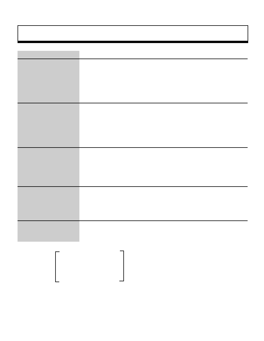
Matrix Function
88
void
slRotYSC
Adding Y axis rotation with sine and cosine specified
Format
void slRotYSC(sn , cs)
FIXED sn ;
FIXED cs ;
Parameters
sn
Angle of rotation versus Y axis after sine transformation
cs
Angle of rotation versus Y axis after cosine transformation
Function
This function specifies the sine and cosine and multiplies the values with the Y-
axis rotation matrix. The rotation matrix is expressed as shown below.
Return Value
None
Remarks
cs
0.0
-sn
Rysc
=
0.0
1.0
0.0
s n
0.0
cs
0.0
0.0
0.0
Note: "cs" and "sn" are the parameter substitution values
Refer to: Chapter 4, "Coordinate Transformation"
slRotYSC
|
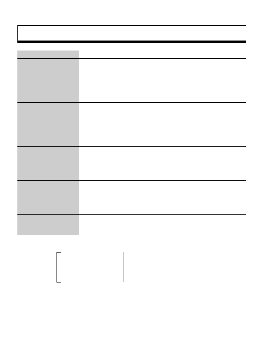
Matrix Function
89
void
slRotZ
Adding rotation around Z axis to current matrix
Format
void slRotZ(angz)
ANGLEangz ;
Parameters
angz
Angle of rotation around Z axis
Function
This function multiplies a Z axis rotation matrix with the current matrix. The rotation
matrix is expressed below.
Return Value
None
Remarks
cosÆ
sinÆ
0.0
Rz
=
-sinÆ
cosÆ
0.0
0.0
0.0
1.0
0.0
0.0
0.0
a)Rotation matrix for adding rotation around the Z axis
Refer to: Chapter 4, "Coordinate Transformation"
slRotZ
|
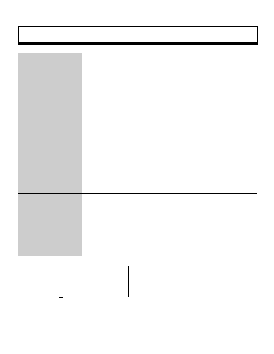
Matrix Function
90
void
slRotZSC
Adding Z axis rotation with sine and cosine specified
Format
void slRotZSC(sn , cs)
FIXED sn ;
FIXED cs ;
Parameters
sn
Angle of rotation versus Z axis after sine transformation
cs
Angle of rotation versus Z axis after cosine transformation
Function
This function specifies the sine and cosine and multiplies the values with the Z-
axis rotation matrix. The rotation matrix is expressed as shown below.
Return Value
None
Remarks
cs
s n
0.0
Rzsc
=
-sn
cs
0.0
0.0
0.0
1.0
0.0
0.0
0.0
Note: "cs" and "sn" are the parameter substitution values
Refer to: Chapter 4, "Coordinate Transformation
slRotZSC "
|

Matrix Function
91
void
slScale
Current matrix scaling
Format
void slScale(sx , sy , sz)
FIXED sx ;
FIXED sy ;
FIXED sz ;
Parameters
sx
Enlargement/reduction ratio in the direction of the X axis
sy
Enlargement/reduction ratio in the direction of the Y axis
sz
Enlargement/reduction ratio in the direction of the Z axis
Function
This function multiplies the enlargement/reduction ratio matrix by the current
matrix. The enlargement/reduction matrix is expressed below.
Return Value
None
Remarks
sx
0.0
0.0
Rxyz
=
0.0
sy
0.0
0.0
0.0
sz
0.0
0.0
0.0
Note: "sx","sy", and "sz" are parameter substitution values
Refer to: Chapter 4, "Coordinate Transformation"
slScale
|

Matrix Function
92
void
slTranslate
Current matrix movement
Format
void slTranslate(tx , ty , tz)
FIXED tx ;
FIXED ty ;
FIXED tz ;
Parameters
tx
Movement in the direction of the X axis
ty
Movement in the direction of the Y axis
tz
Movement in the direction of the Z axis
Function
This function multiplies the parallel movement matrix with the current matrix. The
parallel movement matrix is expressed as shown below.
Return Value
None
Remarks
1.0
0.0
0.0
Txyz
=
0.0
1.0
0.0
0.0
0.0
1.0
tx
ty
tz
Note: "tx", "ty" and "tz" are the parameter substitution values.
Refer to: Chapter 4, "Coordinate Transformation"
slTranslate
|
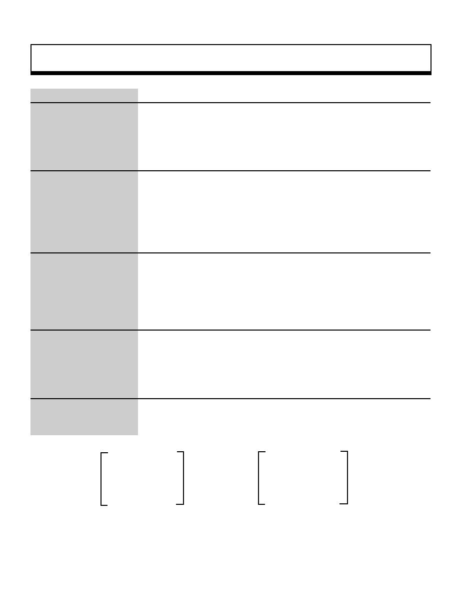
Matrix Function
93
void
slTransposeMatrix
Current matrix transposition
Format
vioid slTransposeMatrix()
Parameters
None
Function
This function replaces the current matrix with a transposed matrix
(Zero movement in parallel direction)
Return Value
None
Remarks
A transposed matrix is expressed as shown below.
M00 , M01 , M02
M00 , M10 , M20
M10 , M11 , M12
_Ë
M01 , M11 , M21
M20 , M21 , M22
M02 , M12 , M22
0.0 , 0.0 , 0.0
0.0 , 0.0 , 0.0
a)Original matrix
b)Transposed matrix
Refer to:
slTransposeMatrix
Conversion to transposed matrix
|
Matrix Function
94
void
slUnitMatrix
Make specified matrix a unit matrix
Format
void ulUjnitMatrix(mtptr)
MATRIXmtptr ;
Parameters
mtptr
Starting address of MATRIX-type variable to be converted to a unit matrix
(input)
Function
This function converts the specified matrix into a unit matrix. If CURRENT is
specified for the parameter, this function changes the current matrix into a unit
matrix.
Return Value
None
Remarks
Refer to: Chapter 5, "Matrices"
slUnitMatr
|

Mathematical Operation Function
95
Uint16
slAng2Dec
Convert ANGLE-type angle value into BCD-type value
Format
Uint16 slAng2Dec(ang)
ANGLE ang;
Parameters
ang
ANGLE-type angle value
Function
This function converts an ANGLE-type angle value into a BCD-type value.
Return Value
Angle data converted into a BCD-TYPE VALUE
Remarks
LISTING
402=400 _¨ 0x0090
ang=0x1000 _¨ 0x0022
Refer to: Chapter 11, "Mathematical Operation Functions
slAng2Dec
|

Mathematical Operation Function
96
void
slAng2FX
Convert ANGLE-type angle value into FIXED-type value
Format
FIXED slang2FX(ang)
angle amg;
Parameters
ang
ANGLE-type angle value
Function
This function converts an ANGLE-type angle value into a FIXED-type value.
Return values:
Return Value
Angle data converted into a FIXED-type value
Remarks
Ex.:
ang = 0X4000 _¨ 0x005A0000 (90.0)
ang = 0X1000 _¨ 0x0016800 (22.5)
Refer to: Chapter 11, "Mathematical Operation Functions"
slAng2FX
|

Mathematical Operation Function
97
Uint16
slAng2Hex
Convert ANGLE-type angle value into hexadecimal value
Format
Uint16 slAng2Hex(ang)
ANGLE ang ;
Parameters
ang
ANGLE-type angle value
Function
This function converts an ANGLE-type angle value into a hexadecimal value.
Return Value
Angle data converted into a hexadecimal value
Remarks
Ex.:
ang = 0X4000 _¨ 0x005A
ang = 0X1000 _¨0X0016
Refer to: Chapter 11, "Mathematical Operation Functions"
slAng2Hex
|
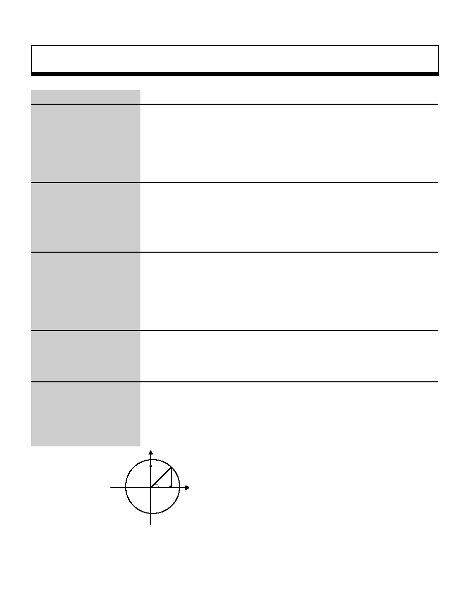
Mathematical Operation Function
98
ANGLE
slAtan
Return angle of specified direction
Format
ANGLE slAtan(tx, ty)
FIXED tx;
fixed TY;
Parameters
tx
X component of vector in specified direction
ty
Y component of vector in specified direction
Function
This function returns the angle of the specified direction..
Return Value
Returns the angle of the specified direction.
Remarks
The diagram below illustrates the principles behind the angle calculation in the
function "slAtan".
Refer to: Chapter 11, "Mathematical Operation Functions
slAtan
Æ
Y
X
ty
tx
tanÆ = ty/tx ;
Æ= tan
-1
ty/tx = slAtan(tx , ty) ;
|

Mathematical Operation Function
99
void
slCalcPoint
Multiply current matrix with specified point and substitute
Format
void slCalcPoint(x,y,z,ans)
FIXED *x,y,z;;
FIXED *ans ;
Parameters
x
X component of transformation coordinate specification
y
Y component of transformation coordinate specification
z
Z component of transformation coordinate specification
ans[XYZ]
XYZ component substitution variable after matrix transformation
Function
This function multiplies the XYZ coordinate values specified as parameters with
the current matrix and substitutes the result into the parameter "ans[XYZ]".
Return Value
None
Remarks
Refer to: Chapter 11, "Mathematical Operation Functions
slCalcPoint
|

Mathematical Operation Function
100
FIXED
slCos
Returns cosine value of specified angle
Format
FIXED slCos(angc)
ANGLE ANGC;
Parameters
angc
Specified angle
Function
This function gets the cosine value for the specified angle from a Cos table.
Return Value
The function returns the cosine value for the specified angle.
Remarks
Cosine values are represented in the range 0x0000 to 0xffff. However, because
0x0008 is added to the angle data and the four low-order bits are discarded
(rounding 7 down and 8 up), with the result that the range 0x0000 to 0xfff0 is
used for the angle data, the precision of the operation results suffers slightly.
This treatment applies to all functions that use angle data.
Refer to: Chapter 11, "Mathematical Operation Functions"
slCos
|
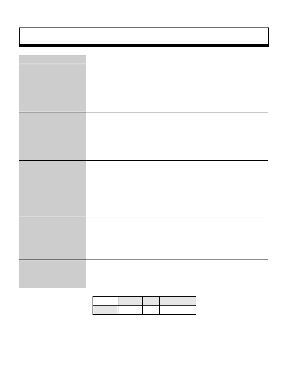
Mathematical Operation Function
101
Uint32
slDec2Hex
Convert BCD code to hexadecimal code
Format
Uint32 slDec2Hex(val)
Uint32 val ;
Parameters
val
BCD code to be converted
Function
This function converts a BCD code to a hexadecimal code.
Return Value
This function returns the converted hexadecimal code.
Remarks
BCD code: notation for representing the values 0 to 9 using 4 bits.
(Ex.: The decimal value "128" is represented in BCD notation as "0x128")
Decimal BCD Hexadecimal
Notation
92
0x92
0x5c
Note: Example of representations of a value using each form of notation.
Refer to: Chapter 11, "Mathematical Operation Functions"
slDec2Hex
|

Mathematical Operation Function
102
FIXED
slDivFX
Division operation (B/A)
Format
FIXED slDivFX(a , b)
FIXED s ;
FIXED b ;
Parameters
a
A in "B/A": divisor
b
B in "B/A": dividend
Function
This function divides one fixed-point decimal by another (B/A).
Return Value
This function returns the result of "B/A".
Remarks
This function does not perform an overflow check.
Refer to: Chapter 11, "Mathematical Operation Functions"
slDivFX
|

Mathematical Operation Function
103
Uint32
slHex2Dec
Convert hexadecimal code to BCD code
Format
Uint32 slHex2Dec(val))
Uint32 val ;
Parameters
val
Hexadecimal code to be converted
Function
This function converts a hexadecimal code to a BCD code.
Return Value
This function returns the converted BCD code.
Remarks
BCD code: notation for representing the values 0 to 9 using 4 bits.
(Ex.: The decimal value "128" is represented in BCD notation as "0x128")
Decimal BCD Hexadecimal
Notation
92
0x92
0x5c
Note: Example of representations of a value using each form of notation
Refer to: Chapter 11, "Mathematical Operation Functions"
slHex2Dec
|
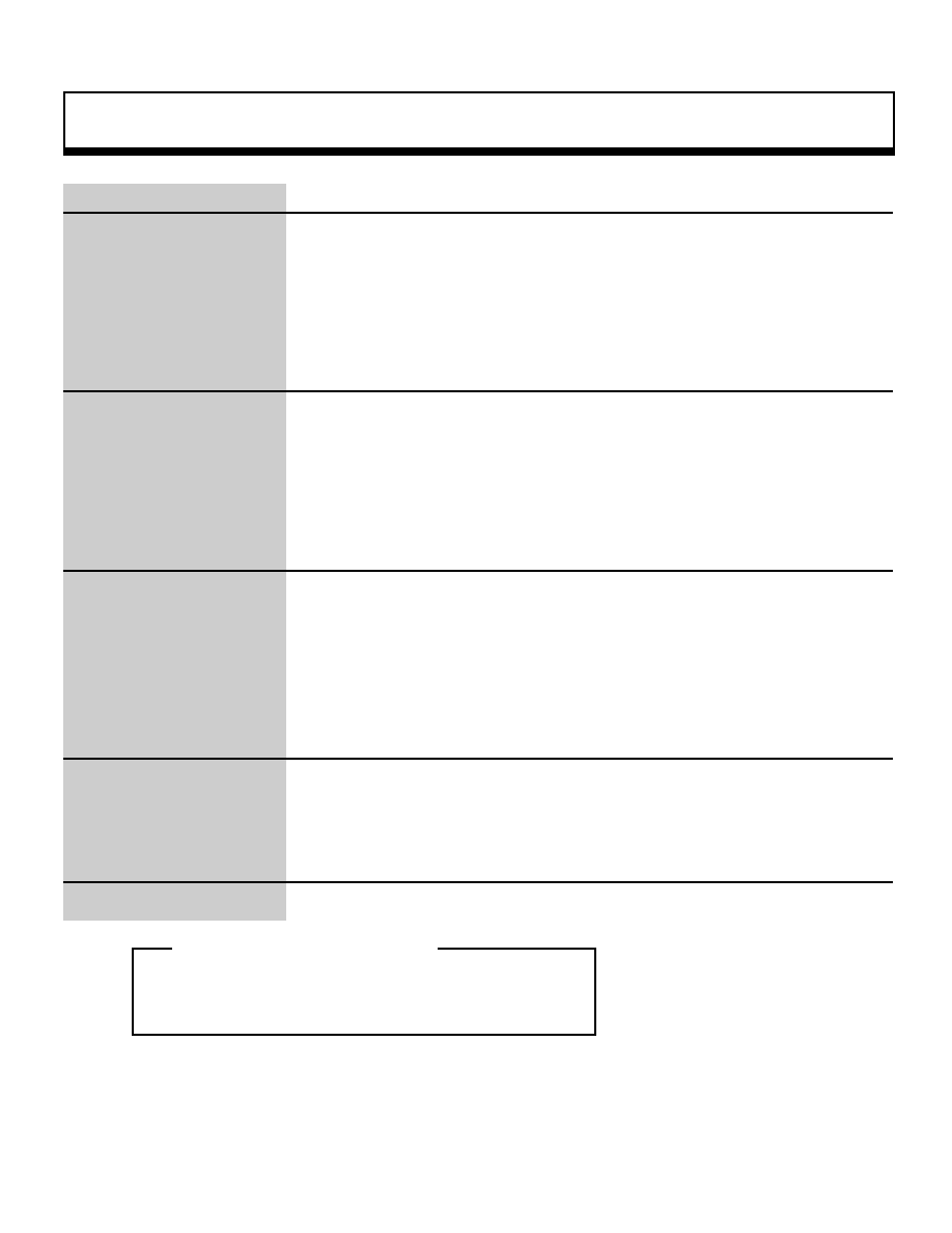
Mathematical Operation Function
104
FIXED
slInnerProduct
Inner product of vectors
Format
FIXED slInnerProduct(vctl , vct2)
VECTOR vct 1 ;
VECTOR vct2 ;
Parameters
vct1
VECTOR-type variable for which the inner product is to be taken
vct2
VECTOR-type variable for which the inner product is to be taken
Function
This function finds the inner product of the specified vectors and returns the result
Return Value
This function returns the result of the inner product operation.
Remarks
The return value is calculated as shown below.
A(X1,Y1,Z1)*B(X2,Y2,Z2) = X1*X2+Y1*Y2+Z1*Z2
= Return Value
Refer to: Chapter 11, "Mathematical Operation Functions"
slInnerProduct
_oe
Inner product of vectors
_oe
|
Mathematical Operation Function
105
FIXED
slMulFX
Multiplication operation (A * B)
Format
FIXED slMulFX(a , b)
FIXED a :
FIXED b ;
Parameters
a
A in "A * B": multiplier
b
B in "A * B": multiplicand
Function
This function multiplies two fixed-point decimals together
Return Value
This function returns the product of A and B.
Remarks
Refer to: Chapter 11, "Multiplication Operation Functions"
slMulFX
|

Mathematical Operation Function
106
FIXED
slRandom
Random number generator
Format
FIXED slRandom()
Parameters
None
Function
This function generates a random FIXED-type value in a range from 0 to 1.
Return Value
A FIXED-type value ranging from 0.0 to 1.0
Remarks
Refer to:
slRandom
|

Mathematical Operation Function
107
FIXED
slSin
Returns sine value of specified angle
Format
FIXED slSin(angs)
ANGLE angs ;
Parameters
angs
Specified angle
Function
This function gets the sine value for the specified angle from a Sin table.
Return Value
The function returns the sine value for the specified angle.
Remarks
Sine values are represented in the range 0x0000 to 0xffff. However, because
0x0008 is added to the angle data and the four low-order bits are discarded
(rounding 7 down and 8 up), with the result that the range 0x0000 to 0xfff0 is
used for the angle data, the precision of the operation results suffers slightly.
This treatment applies to all functions that use angle data.
Refer to: Chapter 11, "Mathematical Operation Functions"
slSin
|

Mathematical Operation Function
108
Uint32
slSquart
Calculate square root of unsigned integer value
Format
Uint32 slSqart(sqrt))
Uint32 sqrt ;
Parameters
sqrt
Unsigned integer value
Function
This function calculates the square root of an unsigned integer value.
Return Value
This function returns the square root of an unsigned integer value.
Remarks
BCD code: notation for representing the values 0 to 9 using 4 bits.
Refer to: Chapter 11, "Mathematical Operation Functions"
slSquart
|

Mathematical Operation Function
109
FIXED
slSquartFX
Calculate square root of unsigned fixed-point decimal
Format
FIXED slSquartFX(sqrtx)
FIXED sqrtfx ;
Parameters
sqrtfx
Unsigned fixed-point decimal
Function
This function calculates the square root of an unsigned fixed-point decimal.
Return Value
This function returns the square root of an unsigned fixed-point decimal.
Remarks
Because the calculation is performed as for integers, the precision of the result is
8 bits for the integer portion and 8 bits for the decimal portion.
Refer to: Chapter 11, "Mathematical Operation Functions"
slSquartFX
|

Mathematical Operation Function
110
FIXED
slTan
Returns tangent value of specified angle
Format
FIXED slTan(angt)
ANGLE ngt ;
Parameters
angt
Specified angle
Function
This function gets the tangent value for the specified angle from a table.
Return Value
The function returns the tangent value for the specified angle
Remarks
Tangent values are represented in the range 0x0000 to 0xffff. However, because
0x0008 is added to the angle data and the four low-order bits are discarded
(rounding 7 down and 8 up), with the result that the range 0x0000 to 0xfff0 is
used for the angle data, the precision of the operation results suffers slightly.
This treatment applies to all functions that use angle data.
Refer to: Chapter 11, "Mathematical Operation Functions"
slTan
|

Event Management Function
111
Void
slCloseEvent
Event decision
Format
void siCloseEvent(evptr)
EVENT *evptr :
Parameters
evptr
Starting address of area where event to be deleted is stored
Function
This function removes an event registered in the execution list from the list and
releases its area. If a work area was also allocated, that area is also released.
Return Value
None
Remarks
If an event that is not registered in the event list is specified, list modification
processing will be executed on the wrong event due to the incorrect list
information, with information being written to unpredictable addresses and, in the
worst case, the CPU may stop operating.
Refer to: Chapter 10, "Event Control"
slCloseEvent
|

Event Management Function
112
void
slExecuteEvent
Event schedule management
Format
void slExecuteEvent()
Parameters
None
Function
This function executes the events registered in the execution list in sequence,
starting from the top of the list.
:
.
Return Value
None
Remarks
The function "slExecuteEvent" should be called once per frame
Refer to: Chapter 10, "Event Control"
slExecuteEvent
|
Event Management Function
113
EVENT
slGetEvent
Get area equal in size to event
Format
EVENT*slGetEvent()
Parameters
None
Function
This function gets an area that is the same size as an event (128 bytes) in the
part of RAM that has been allocated for events and returns the pointer to that
area.
Because this function only gets an area equal in size to an event from the event
area; this function does not register that area as an event.
Return Value
Pointer to the RAM area that was gotten. NULL is returned if no area was
available. (There is a maximum limit of 64 events.)
Remarks
The RAM area gotten by "slGetEvent" must be released (using the function
"slReturnEvent") when the event using the area is closed.
If the area is not released, the area will continue to exist, unused, in the event
area.
Refer to: Chapter 10, "Event Control"
slGetEvent
|

Event Management Function
114
WORK
slGetWork
Get new work
Format
WORK*slGetWork()
Parameters
None
Function
This function gets a RAM area allocated for use as a work area and returns the
pointer for that area.
Return Value
This function returns the starting address for the new work area.
The NULL value is returned if the area could not be gotten (due to maximum of
256
work areas).
Remarks
Refer to: Chapter 10, "Event Control"
Refer to: Chapter 10, "Event Control"
slGetWork
|

Event Management Function
115
void
slInitEvent
Event processing initialization
Format
void slInitEvent()
Parameters
None
Function
This function initializes the event and work management buffers. After
initialization, 64 event areas and 256 work areas are allocated within memory.
Return Value
None
Remarks
The event and work RAM itself is not initialized. Initialize the RAM in the user
program after getting these areas.
Refer to: Chapter 10, "Event Control"
slInitEvent
|

Event Management Function
116
void
slReturnEvent
Release area allocated by "slGetEvent"
Format
void slReturnEvent(evptr)
EVENT*evptr ;
Parameters
evptr
Starting address of area to be released
Function
This function releases an area allocated by the "slGetEvent" function and returns
it to the system.
Return Value
None
Remarks
When an area registered as an event is released by using the "slReturnEvent"
function, the area is returned to the system, but because the event list is not
altered (and the function does not check to see if the area was an event area),
problems may arise with functions executed subsequently, such as "slGetEvent",
"slSetEvent", and "slSetEventNext".
Always call the function "slCloseEvent" and release the event registration.
Refer to: Chapter 10, "Event Control"
slReturnEvent
|

Event Management Function
117
void
slReturnWork
Return work area to system
Format
void slReturnWork(wkptr)
WORK*wkptr ;
Parameters
wkptr
Starting address of work area to be returned to system
Function
This function returns a RAM area used as a work area to the system.
Return Value
This function returns the converted hexadecimal code.
Remarks
Although the pointer returned to the system is registered again in the system
buffer, the system does not check to see if the pointer that was returned is already
registered or not. As a result, it is essential to be aware that if the same pointer is
returned several times, problems can arise when "slGetWork" is executed later,
such as multiple events using the same work area.
Refer to: Chapter 10, "Event Control"
slReturnWork
|

Event Management Function
118
EVENT
slSetEvent
Event registration
Format
EVENT*slSetEvent(func)
void(*func)() ;
Parameters
func
Pointer for function being registered as an event
Function
This function gets an event area and appends the event to the end of the event
list. The "func" specified as the function to be executed by this event is
registered.
Return Value
When the event area is gotten successfully, this function returns the starting
address of the registered event area. If there are no available event areas, this
function returns the NULL code.
Remarks
Although the event area is allocated as 128 bytes, the first 16 bytes are used by
the system.
Refer to: Chapter 10, "Event Control"
slSetEvent
|

Event Management Function
119
EVENT
slSetEventNext
Add new event after specified event
Format
EVENT*slSetEventNext(evptr , func)
EVENT*evptr ;
void(*func)()
Parameters
evptr
Starting address of the event area immediately preceding the position
where the new event is to be inserted
func
Pointer for function to be registered as an event
Function
This function gets an event area and inserts/adds it to the event list. The new
event is registered in the event list so that it is executed next after the event
specified as a parameter.
Return Value
This function returns the starting address of the registered event area. If there are
no more event areas remaining, the event is not registered and this function
returns the NULL code.
Remarks
Although the event area is allocated as 128 bytes, the first 16 bytes are used by
the system.
Refer to: Chapter 10, "Event Control"
slSetEventNext
|

System Management Function
120
Uint8
slCheckReset
Get SMPC reset button status
Format
Uint8 slCheckReset()
Parameters
None
Function
This function gets the reset button status when system reset by the reset button is
disabled.
Return Value
SMPC reset button status
Remarks
The following values are returned for the return value:
SMPC_RES_OFF
Reset button off (initial value)
SMPC_RES_ON Reset button on
Once the status goes to on, it does not change until "slClearReset" is called.
Refer to: HARDWARE MANUAL vol. 1 (SMPC)
slCheckReset
|

System Management Function
121
Uint8
slGetLanguage
Get SMPC memory language number
Format
Uint8 slGetLanguage ()
Parameters
None
Function
This function gets the language number from the SMPC memory information.
Return Value
Language number
Remarks
The SMPC memory information can also be referenced from the global variable
"Smpc_Status".
To get the newest SMPC status for the SMPC memory information, use
"slGetStatus". The following values are returned for the return value:
SMPC_ENGLISH
English
SMPC_DEUTSCH
German
SMPC_FRANCAIS
French
SMPC_ESPANOL
Spanish
SMPC_ITALIANO
Italian
SMPC_JAPAN
Japanese
Refer to: HARDWARE MANUAL vol. 1 (SMPC)
slGetLanguage
|

System Management Function
122
Bool
slGetPeripheral
Interrupt back (get peripheral data only)
Format
Bool slGetPeripheral ()
Parameters
None
Function
This function automatically gets the peripheral data and puts it into the global
variable "Smpc_Peripheral".
This function also automatically gets the number of connected peripherals and
puts the data into the global variables "Per_Connect1" and "Per_Connect2".
Return Value
Execution results
OK: Successful
NG: Failed
Remarks
Execution of this function fails when the semaphore cannot be gotten (because it
is locked by another process). Because this function is called by "slInitSystem"
when the library is started up, there is no particular need to call this
function
unless you are changing the settings.
The settings are reflected in the data starting from the second frame after the
settings are made.
Execution of this function fails when the peripheral port input/output setting is
incorrect.
Refer to: HARDWARE MANUAL vol. 1 (SMPC)
slGetPeripheral
|

System Management Function
123
Uint8
slGetSoundOutput
Get SMPC memory sound output mode
Format
Uint8 slGetSoundOutput()
Parameters
None
Function
This function gets the sound output mode from the SMPC memory information.
Return Value
Sound output mode
Remarks
The SMPC memory information can also be referenced from the global variable
"Smpc_Status".
To get the newest SMPC status for the SMPC memory information, use
"slGetStatus". The following values are returned for the return value:
SMPC_SOUND_STEREO Stereo
SMPC_SOUND_MONO
Monaural
Refer to: HARDWARE MANUAL vol. 1 (SMPC)
slGetSoundOutput
|

System Management Function
124
Bool
slGetStatus
Interrupt back (get SMPC status and peripheral data
Format
Bool slGetStatus ()
Parameters
None
Function
This function automatically gets the latest SMPC status and puts it into the global
variable "Smpc_Status".
This function also automatically gets the peripheral data and puts it into the global
variable "Smpc_Peripheral".
This function also automatically gets the number of connected peripherals and
puts the data into the global variables "Per_Connect1" and "Per_Connect2".
Return Value
Execution results
OK: Successful
NG: Failed
Remarks
Execution of this function fails when the semaphore cannot be gotten (because it
is locked by another process). This function is called once by "slInitSystem" when
the library is started up to get the SMPC status at startup.
Afterwards, the mode is set so that "slGetPeripheral" is called so that only the
peripheral data is gotten.
The settings are reflected in the data starting from the second frame after the
settings are made.
Execution of this function fails when the peripheral port input/output setting is
incorrect.
Refer to: HARDWARE MANUAL vol. 1 (SMPC)
slGetStatus
|

System Management Function
125
Void
slInitPeripheral
System management and peripheral control initialization
Format
void slInitPeripheral()
Parameters
None
Function
This function initializes the system management and peripheral control library.
Return Value
None
Remarks
Because this function is called by "slInitSystem" during library startup, there is no
particular need to call this function.
Refer to: HARDWARE MANUAL vol. 1 (SMPC)
slInitPeripheral
|

System Management Function
126
Bool
slIntBackCancel
Clear flags sets for interrupt back
Format
Bool slIntBackCancel ()
Parameters
None
Function
This function clears the settings that were made by calling "slGetPeripheral" and
"slGetStatus" indicating that the SMPC status and peripheral data are to be
gotten automatically.
Return Value
Execution results
OK: Successful
NG: Failed
Remarks
Execution of this function fails when the semaphore cannot be gotten (because it
is locked by another process).
Refer to: HARDWARE MANUAL vol. 1 (SMPC)
slIntBackCancel
|

System Management Function
127
Bool
slResetDisable
Reset disable (no wait mode)
Format
Bool slResetDisable ()
Parameters
None
Function
This function disables system reset by pressing the reset button.
Return Value
Execution results
OK: Successful
NG: Failed
Remarks
Execution of this function fails when the semaphore cannot be gotten (because it
is locked by another process).
This function does not wait for the termination of SMPC command execution.
If an interrupt back has been issued, this function is queued in the command
cache.
Execution of this function fails if a command cache overflow occurs.
Refer to: HARDWARE MANUAL vol. 1 (SMPC)
slResetDisable
|

System Management Function
128
Bool
slResetDisableWait
Reset disable (wait mode)
Format
Bool slResetDisableWait ()
Parameters
None
Function
This function disables system reset by pressing the reset button.
Return Value
Execution results
OK: Successful
NG: Failed
Remarks
Execution of this function fails when the semaphore cannot be gotten (because it
is locked by another process). This function waits for the termination of SMPC
command execution.
If an interrupt back has been issued, execution of this function fails.
Refer to: HARDWARE MANUAL vol. 1 (SMPC)
slResetDisableWait
|

System Management Function
129
Bool
slResetEnable
Reset enable (no wait mode)
Format
Bool slResetEnable ()
Parameters
None
Function
This function enables system reset by pressing the reset button.
Return Value
Execution results
OK: Successful
NG: Failed
Remarks
Execution of this function fails when the semaphore cannot be gotten (because it
is locked by another process). This function does not wait for the termination of
SMPC command execution.
If an interrupt back has been issued, this function is queued in the command
cache.
Execution of this function fails if a command cache overflow occurs.
Refer to: HARDWARE MANUAL vol. 1 (SMPC)
slResetEnable
|
System Management Function
130
Bool
slResetEnableWait
Reset enable (wait mode)
Format
Bool slResetEnableWait ()
Parameters
None
Function
This function enables system reset by pressing the reset button.
Return Value
Execution results
OK: Successful
NG: Failed
Remarks
Execution of this function fails when the semaphore cannot be gotten (because it
is locked by another process). This function waits for the termination of SMPC
command execution.
If an interrupt back has been issued, execution of this function fails.
Refer to: HARDWARE MANUAL vol. 1 (SMPC)
slResetEnableWait
|

System Management Function
131
Void
slSetLanguage
Set SMPC memory language number
Format
void slSetLanguage(lang)
Uint8 lang ;
Parameters
Language number
Function
This function sets the language number in the SMPC memory information.
Return Value
None
Remarks
The SMPC memory information can also be referenced from the global variable
"Smpc_Status".
To store the SMPC memory information in the SMPC memory, use
"slSetSmpcMemory".
The following values can be used for the parameters:
SMPC_ENGLISH
English
SMPC_DEUTSCH
German
SMPC_FRANCAIS
French
SMPC_ESPANOL
Spanish
SMPC_ITALIANO
Italian
SMPC_JAPAN
Japanese
Refer to: HARDWARE MANUAL vol. 1 (SMPC)
slSetLanguage
|

System Management Function
132
Bool
slSetSmpcMemory
SMPC memory setting (no wait mode)
Format
Bool slSetSmpcMemory()
Parameters
None
Function
This function sets the SMPC memory.
Return Value
Execution results
OK: Successful
NG: Failed
Remarks
Execution of this function fails when the semaphore cannot be gotten (because it
is locked by another process).
This function does not wait for the termination of SMPC command execution.
If an interrupt back has been issued, this function is queued in the command
cache.
Execution of this function fails if a command cache overflow occurs.
This function sets the contents of the global variable "Smpc_Status" in the SMPC
memory.
Refer to: HARDWARE MANUAL vol. 1 (SMPC)
slSetSmpcMemory
|

System Management Function
133
Bool
slSetSmpcMemoryWait
SMPC memory setting (wait mode)
Format
Bool slSetSmpcMemoryWait()
Parameters
None
Function
This function sets the SMPC memory.
Return Value
Execution results
OK: Successful
NG: Failed
Remarks
Execution of this function fails when the semaphore cannot be gotten (because it
is locked by another process).
This function waits for the termination of SMPC command execution.
If an interrupt back has been issued, execution of this function fails.
This function sets the contents of the global variable "Smpc_Status" in the SMPC
memory.
Refer to: HARDWARE MANUAL vol. 1 (SMPC)
slSetSmpcMemoryWait
Void
|

System Management Function
134
slSetSoundOutput
Set SMPC memory sound output mode
Format
void slSetSoundOutput(mode)
Uint8 mode ;
Parameters
mode
Sound output mode
Function
This function sets the sound output mode in the SMPC memory information.
Return Value
None
Remarks
The SMPC memory information can also be referenced from the global variable
"Smpc_Status".
To store the SMPC memory information in the SMPC memory, use
"slSetSmpcMemory".
The following values can be used for the parameters:
SMPC_SOUND_STEREO Stereo
SMPC_SOUND_MONO
Monaural
Refer to: HARDWARE MANUAL vol. 1 (SMPC)
slSetSoundOutput
Bool
|
System Management Function
135
slSlaveOff
Slave SH2 off (no wait mode)
Format
Bool slSlaveoff ()
Parameters
None
Function
This function turns the slave SH2 off.
Return Value
Execution results
OK: Successful
NG: Failed
Remarks
Execution of this function fails when the semaphore cannot be gotten (because it
is locked by another process).
This function does not wait for the termination of SMPC command execution.
If an interrupt back has been issued, this function is queued in the command
cache.
Execution of this function fails if a command cache overflow occurs.
Refer to: HARDWARE MANUAL vol. 1 (SMPC)
slSlaveOff
Bool
|

System Management Function
136
slSlaveOffWait
Slave SH2 off (wait mode)
Format
Bool slSlaveoffWait ()
Parameters
None
Function
This function turns the slave SH2 off.
Return Value
Execution results
OK: Successful
NG: Failed
Remarks
Execution of this function fails when the semaphore cannot be gotten (because it
is locked by another process).
This function waits for the termination of SMPC command execution.
If an interrupt back has been issued, execution of this function fails.
Refer to: HARDWARE MANUAL vol. 1 (SMPC)
slSlaveOffWait
Bool
|

System Management Function
137
slSlaveOn
Slave SH2 on (no wait mode)
Format
Bool slSlaveon ()
Parameters
None
Function
This function turns the slave SH2 on.
Return Value
Execution results
OK: Successful
NG: Failed
Remarks
Execution of this function fails when the semaphore cannot be gotten (because it
is locked by another process).
This function does not wait for the termination of SMPC command execution.
If an interrupt back has been issued, this function is queued in the command
cache.
Execution of this function fails if a command cache overflow occurs.
Refer to: HARDWARE MANUAL vol. 1 (SMPC)
slSlaveOn
Bool
|

System Management Function
138
slSlaveOnWait
Slave SH2 on (wait mode)
Format
Bool slSlaveonWait ()
Parameters
None
Function
This function turns the slave SH2 on.
Return Value
Execution results
OK: Successful
NG: Failed
Remarks
Execution of this function fails when the semaphore cannot be gotten (because it
is locked by another process).
This function waits for the termination of SMPC command execution.
If an interrupt back has been issued, execution of this function fails.
Refer to: HARDWARE MANUAL vol. 1 (SMPC)
slSlaveOnWait
|

Peripheral Control Function
139
Uint8
slGetOptimize
Get peripheral acquisition time optimization mode
Format
Uint8 slGetOptimize ()
Parameters
None
Function
This function gets the peripheral acquisition time optimization mode.
Return Value
Peripheral acquisition time optimization mode
Remarks
The following values are returned for the return value.
SMPC_OPT_ENA
Acquisition time optimization enable (initial value)
SMPC_OPT_DIS
Acquisition time optimization disable
Refer to: HARDWARE MANUAL vol. 1 (SMPC)
slGetOptimize
|

Peripheral Control Function
140
Uint8
slGetPortMode1,2
Get port mode for peripheral port 1, 2
Format
Uint8 slGetPortMode1 ()
Uint8 slGetPortMode2 ()
Parameters
None
Function
These functions get the port mode of peripheral ports 1 and 2.
Return Value
Port mode of the peripheral port
Remarks
The following values are returned for the return value.
SMPC_PORT_15
15-byte mode (initial value)
SMPC_PORT_255
255-byte mode
SMPC_PORT_ZERO
0-byte mode
Refer to: HARDWARE MANUAL vol. 1 (SMPC)
slGetPortMode1,2
|

Peripheral Control Function
141
Bool
slSetOptimize
Set peripheral acquisition time optimization mode
Format
Bool slSetOptimize(mode)
Uint8 mode ;
Parameters
mode
Peripheral acquisition time optimization mode
Function
This function sets the peripheral acquisition time optimization mode.
Return Value
Execution results
OK: Success
NG: Failure
Remarks
Execution of this function fails when the semaphore cannot be gotten (because
it is locked by another process).
The following values can be used for the parameter.
SMPC_OPT_ENA
Acquisition time optimization enable (initial value)
SMPC_OPT_DIS
Acquisition time optimization disable
Refer to: HARDWARE MANUAL vol. 1 (SMPC)
slSetOptimize
|

Peripheral Control Function
142
Bool
slSetPortMode1,2
Set port mode for peripheral port 1, 2
Format
Bool slSetPortMode1(mode)
Bool slSetPortMode2(mode)
Uint8 mode ;
Parameters
mode
Port mode of peripheral port
Function
These functions set the port mode of peripheral ports 1 and 2.
Return Value
Execution results
OK: Success
NG: Failure
Remarks
Execution of this function fails when the semaphore cannot be gotten (because
it is locked by another process).
The following values can be used for the parameter.
SMPC_PORT_15
15-byte mode (initial value)
SMPC_PORT_255
255-byte mode
SMPC_PORT_ZERO
0-byte mode
Refer to: HARDWARE MANUAL vol. 1 (SMPC)
slSetPortMode1,2
|

Sound Function
143
Bool
slBGMCont
Restart temporarily paused BGM playback
Format
Bool slBGMCont ()
Parameters
None
Function
This function restarts playback of temporarily paused BGM.
Return Value
If the command buffer is full, this function returns the "FALSE" value.
Remarks
Refer to: Chapter 14, "Sound Library"
slBGMCont
|

Sound Function
144
Bool
slBGMFade
Change BGM playback volume
Format
Bool slBGMFade(Volume,Rate)
Uint8 Volume ;
Uint8 Rate ;
Parameters
Volume Volume value
Rate
Rate value
Function
This function gradually changes the BGM playback volume.
Return Value
If the command buffer is full, this function returns the "FALSE" value.
Remarks
Specify a value from 0 to 127 for the parameter "Volume" and a value from 0 to
255 for the parameter "Rate".
"Rate" specifies the interval for changing from the present volume to the specified
volume.
When "Rate" is specified as "0", the volume changes immediately to the value
specified by "Volume".
Refer to: Chapter 14, "Sound Library"
slBGMFade
|

Sound Function
145
Bool
slBGMOff
Stop BGM playback
Format
Bool slBGMOff ()
Parameters
None
Function
This function stops BGM playback.
Return Value
If the command buffer is full, this function returns the "FALSE" value.
Remarks
Refer to: Chapter 14, "Sound Library"
slBGMOff
|

Sound Function
146
Bool
slBGMOn
Start BGM playback
Format
Bool slBGMOn(Song, Prio, Volume, Rate)
Uint 16 Song ;
Uint 8 Prio ;
Uint 8 Volume ;
Uint 8 Rate
Parameters
Song
Sound control number
Prio
Priority value
Volume Volume value
Rate
Rate value
Function
This function starts BGM playback.
Return Value
If the command buffer is full, this function returns the "FALSE" value.
Remarks
BGM always uses sound control number 0.
Specify the parameter "Prio" with a value from 0 to 31. The larger the value, the
higher the priority.
Specify a value from 0 to 127 for the parameter "Volume" and a value from 0 to
255 for the parameter "Rate".
"Rate" specifies the interval for changing from volume value 0 to the specified
volume.
When "Rate" is specified as "0", the volume changes immediately to the value
specified by "Volume".
Refer to: Chapter 14, "Sound Library"
slBGMOn
|

Sound Function
147
Bool
slBGMPause
Pause BGM playback
Format
Bool slBGMPause()
Parameters
None
Function
This function pauses BGM playback.
Return Value
If the command buffer is full, this function returns the "FALSE" value.
Remarks
Refer to: Chapter 14, "Sound Library"
slBGMPause
|

Sound Function
148
Bool
slBGMStat
BGM playback check
Format
Bool slBGMStat()
Parameters
None
Function
This function checks to determine whether or not BGM is being played back.
Return Value
This function returns "1" when playback is in progress (even if paused) and "0" if
playback is stopped.
Remarks
Refer to: Chapter 14, "Sound Library"
slBGMStat
|

Sound Function
149
Bool
slBGMTempo
Change BGM playback speed
Format
Bool slBGMTempo(Tempo)
Sint16 Tempo ;
Parameters
Tempo Tempo value
Function
This function changes the BGM playback speed.
Return Value
If the command buffer is full, this function returns the "FALSE" value.
Remarks
Specify a value ranging from -32768 to 32767 for the parameter "Tempo".
"Tempo" is the tempo value relative to the standard tempo 0; at 4096 (1000h) the
tempo is doubled, and at -4096 the tempo is halved.
Refer to: Chapter 14, "Sound Library"
slBGMTempo
|

Sound Function
150
Bool
slCDDAOff
Stop CD-D/A output
Format
Bool slCDDAOff ()
Parameters
None
Function
This function stops CD-D/A output.
Return Value
If the command buffer is full, this function returns the "FALSE" value.
Remarks
Refer to:
slCDDAOff
|

Sound Function
151
Bool
slCDDAOn
Start CD-D/A output
Format
Bool slCDDAOn(LLevel, RLevel, LPan, RPan)
Uint8 LLevel ;
Uint8 RLevel ;
Sint8 LPan ;
Sint8 RPan ;
Parameters
LLevel Volume value (left)
RLevel Volume value (right)
LPan
Pan value (left)
RPan
Pan value (right)
Function
This function starts CD-D/A output.
Return Value
If the command buffer is full, this function returns the "FALSE" value.
Remarks
Specify a value in the range from 0 to 127 for the parameters "LLevel" and
"RLevel". (The four low-order bits are ignored, however.)
Specify a value in the range from -127 to 127 for the parameters "LPan" and
"RPan". (-127 (left) <-> 0 (center) <-> 127 (right))
Note that the SCSP pans in 32 steps, so the three low-order "Pan" bits are
ignored.
Refer to:
slCDDAOn
|

Sound Function
152
Bool
slDSPOff
Stop DSP playback
Format
Bool slDSPOff()
Parameters
None
Function
This function stops DSP playback.
Return Value
If the command buffer is full, this function returns the "FALSE" value.
Remarks
Refer to: Chapter 14, "Sound Library"
slDSPOff
|
Sound Function
153
void
slInitSound
Set sound driver and initialize sound control CPU
Format
void slInitSound(Dry, Drvsz, Map, Mapsz)
Uint8 *Dry ;
Uint32 Drvsz ;
Uint8 *Map ;
Uint32 Mapsz ;
Parameters
Drv
Driver file address
Drvsz
Driver file size
Map
Map file address
Mapsz Map file size
Function
This function sets the sound driver and initializes the sound control CPU
(MC68000).
Return Value
None
Remarks
Refer to: Chapter 14, "Sound Library"
slInitSound
|

Sound Function
154
Bool
slPCMOff
Stop playback from PCM sound source
Format
Bool slPCMOff (Pdat)
PCM "Pdat ;
Parameters
Pdat
PCM-type structure data
Function
This function stops PCM playback on the specified channel.
Return Value
If the command buffer is full, this function returns the "FALSE" value.
Remarks
For details on PCM-type structures, refer to the "Structure Reference.
Refer to: Chapter 14, "Sound Library"
slPCMOff
|

Sound Function
155
Sint8
slPCMOn
Start playback from PCM sound source
Format
Sint8 slPCMOn (Pdat, Data, Size)
PCM "Pdat ;
void *Data ;
Uint32 Size ;
Parameters
Pdat
PCM-type structure data
Data
PCM data table address
Size
PCM data table size
Function
This function plays back music (sound effects) from a PCM source.
Return Value
This function returns a value ranging from 0 to 7 after normal termination, "-1" if
the command buffer lacks sufficient space, "-2" if there is no PCM channel
available, and "-3" if the PCM buffer lacks sufficient space.
Remarks
For details on PCM-type structures, refer to the "Structure Reference." PCM
playback initiated by this function terminates when the data ends.
Refer to: Chapter 14, "Sound Library"
slPCMOn
|

Sound Function
156
Bool
slPCMParmChange
Change PCM playback parameters
Format
Bool slPCMParmChange(Pdat)
PCM *Pdat ;
Parameters
Pdat
PCM-type structure data
Function
This function changes the value of each parameter for PCM playback.
Return Value
If the command buffer is full, this function returns the "FALSE" value.
Remarks
For details on PCM-type structures, refer to the "Structure Reference."
Refer to: Chapter 14, "Sound Library"
slPCMParmChange
|

Sound Function
157
Bool
slPCMStat
Check playback on specified PCM channel
Format
Bool slPCMStat(Pdat)
PCM *Pdat ;
Parameters
Pdat
PCM-type structure data
Function
This function checks to determine whether or not PCM playback is in progress on
the specified channel.
Return Value
This function returns "1" if playback is in progress, and "0" if it is not.
Remarks
Refer to: Chapter 14, "Sound Library"
slPCMStat
|

Sound Function
158
Bool
slSequenceCont
Restart generation of paused sound effect
Format
Bool slSequenceCont(Seqnm)
Uint8 Seqnm ;
Parameters
Seqnm Sequence control number
Function
This function resumes generation of a paused sound effect.
Return Value
If the command buffer is full, this function returns the "FALSE" value.
Remarks
Specify a value ranging from 1 to 7 for the parameter "Seqnm".
Refer to: Chapter 14, "Sound Library"
slSequenceCont
|

Sound Function
159
Bool
slSequenceFade
Change volume of specified sound effect
Format
Bool slSequenceFade(Seqnm, Volume, Rate)
Uint8 Seqnm ;
Uint8 Volum
Uint8 Rate
Parameters
Seqnm Sequence control number
Volum Volume value
Rate
Rate value
Function
This function gradually changes the volume of the specified sound effect.
Return Value
If the command buffer is full, this function returns the "FALSE" value.
Remarks
Specify a value ranging from 1 to 7 for the parameter "Seqnm".
Specify a value from 0 to 127 for the parameter "Volume" and a value from 0 to
255 for the parameter "Rate".
"Rate" specifies the interval for changing from the present volume to the specified
volume.
When "Rate" is specified as "0", the volume changes immediately to the value
specified by "Volume".
Refer to: Chapter 14, "Sound Library"
slSequenceFade
|

Sound Function
160
Bool
slSequenceOff
Stop generation of specified sound effect
Format
Bool slSequenceOff(Seqnm)
Uint8 Seqnm ;
Parameters
Seqnm Sequence control number
Function
This function stops generation of the specified sound effect.
Return Value
If the command buffer is full, this function returns the "FALSE" value.
Remarks
Specify a value ranging from 1 to 7 for the parameter "Seqnm".
Refer to: Chapter 14, "Sound Library"
slSequenceOff
|

Sound Function
161
Uint8
slSequenceOn
Start generation of specified sound effect
Format
Uint8 SequenceOn(Song, Prio, Volume, Pan)
Uint16 Song ;
Uint8 Prio ;
Uint8 Volume ;
Sint8 Pan ;
Parameters
Song
Sound control number
Prio
Priority value
Volume Volume value
Pan
Pan value
Function
This function starts generation of the specified sound effect.
Return Value
When this function terminates normally, it returns the sequence control number.
If the command buffer is full, this function returns the "FALSE" value.
Remarks
Specify a value from 0 to 31 for the parameter "Prio". The larger the value, the
higher the priority.
Specify a value from 0 to 127 for the parameter "Volume".
Specify a value in the range from -127 to 127 for the parameter "Pan". (-127 (left)
<-> 0 (center) <-> 127 (right))
Note that the SCSP pans in 32 steps, so the three low-order "Pan" bits are
ignored.
Refer to: Chapter 14, "Sound Library"
slSequenceOn
|

Sound Function
162
Uint8
slSequencePan
Change direction of generation of specified sound effect
Format
Uint8 SequencePan(SEqnm, Pan)
Uint8 Seqnm ;
Sint8 Pan ;
Parameters
Seqnm Sequence control number
Pan
Pan value
Function
This function changes the direction of generation of the specified sound effect.
Return Value
If the command buffer is full, this function returns the "FALSE" value.
Remarks
Specify a value ranging from 1 to 7 for the parameter "Seqnm".
Specify a value in the range from -127 to 127 for the parameter "Pan". (-127 (left)
<-> 0 (center) <-> 127 (right))
Note that the SCSP pans in 32 steps, so the three low-order "Pan" bits are
ignored.
Refer to: Chapter 14, "Sound Library"
slSequencePan
|

Sound Function
163
Bool
slSequenceReset
Initialize parameters for specified sound effect
Format
Bool slSequenceReset(Seqnm)
Uint8 Seqnm ;
Parameters
Seqnm Sequence control number
Function
This function initializes the volume, tempo, and pan settings for the specified
sound effect.
Return Value
If the command buffer is full, this function returns the "FALSE" value.
Remarks
Specify a value ranging from 1 to 7 for the parameter "Seqnm".
Refer to: Chapter 14, "Sound Library"
slSequenceReset
|

Sound Function
164
Bool
slSequenceStat
Check playback of specified sound effect
Format
Bool slSequenceStat(Seqnm)
Uint8 Seqnm ;
Parameters
Seqnm Sequence control number
Function
This function checks to determine whether or not the specified sound effect is
being played back.
Return Value
This function returns "1" if the sound effect is being played back (even if paused),
and "0" if the sound effect is stopped.
Remarks
Refer to: Chapter 14, "Sound Library"
slSequenceStat
|

Sound Function
165
Bool
slSequenceTempo
Change speed of specified sound effect
Format
Bool slSequenceTempo(Seqnm, Tempo)
Uint8 Seqnm ;
Sint16 Tempo ;
Parameters
Seqnm Sequence control number
Tempo Tempo value
Function
This function changes the speed of the specified sound effect.
Return Value
If the command buffer is full, this function returns the "FALSE" value.
Remarks
Specify a value ranging from 1 to 7 for the parameter "Seqnm".
Specify a value ranging from -32768 to 32767 for the parameter "Tempo".
"Tempo" is the tempo value relative to the standard tempo 0; at 4096 (1000h) the
tempo is doubled, and at -4096 the tempo is halved.
Refer to: Chapter 14, "Sound Library"
slSequenceTempo
|

Sound Function
166
Bool
slSndEffect
Switch sound effect by DSP
Format
Bool slSndEffect(Effect)
Uint8 Effect ;
Parameters
Effect
Effect bank number
Function
This function switches the sound effect generated by the DSP.
Return Value
If the command buffer is full, this function returns the "FALSE" value.
Remarks
Specify a value ranging from 1 to 15 for the parameter "Effect".
Refer to:
slSndEffect
|

Sound Function
167
Bool
slSndMapChange
Change current sound map
Format
void *slSndMapChange(Map)
Uint8 Map :
Parameters
Map
Map number
Function
This function changes the current sound map.
Return Value
When this function terminates normally, it returns the address of the command
buffer where the parameters were set.
If there was no space available in the command buffer, the function returns
"FALSE".
Remarks
After sending the sound data, set the "work area transfer completed" bit.
Refer to:
slSndMapChange
|
Sound Function
168
Bool
slSndMixChange
Switch mixer corresponding to tone bank
Format
Bool slSndMixChange(Tbank, Mixno)
Uint8 Tbank ;
Uint8 Mixno ;
Parameters
Tbank Tone bank number
Mixno
Mixer number
Function
This function switches the mixer corresponding to the tone bank
Return Value
If the command buffer is full, this function returns the "FALSE" value.
Remarks
Specify a value ranging from 0 to 15 for the parameter "Tbank".
Specify a value ranging from 0 to 127 for the parameter "Mixno".
Refer to:
slSndMixChange
|

Sound Function
169
Bool
slSndMixParmChange
Change mixer parameters
Format
Bool slSndMixParmChange(Effect, Level, Pan)
Uint8 Effect ;
Uint8 Level ;
Sint8 Pan
Parameters
Effect
DSP effect output channel
Level
Effect return level
Pan
Effect pan
Function
This function changes the mixer parameters.
Return Value
If the command buffer is full, this function returns the "FALSE" value.
Remarks
Specify a value ranging from 0 to 7 for the parameter "Effect".
Specify a value ranging from 0 to 127 for the parameter "Level". (Ignore the four
low-order bits.)
Specify a value ranging from -127 to 127 for the parameter "Pan". (Ignore the
three low-order bits.)
Refer to: Chapter 14, "Sound Library"
slSndMixParmChange
|

Sound Function
170
Sint8
slSndPCMNum
Return available PCM channel number
Format
Sint8 slSndPCMnUM(Mode)
Parameters
PCM playback mode
Function
This function returns the number of an available PCM channel.
Return Value
If this function terminates normally, it returns a value from 0 to 7. If there are no
available PCM channels, the function returns the value "-1".
Remarks
Specify the logical sum of "_Stereo" or "_Mono" and "_16Bit" or "_8Bit" for the
parameter "Mode".
Although PCM permits playback of up to eight "voices," stereo playback requires
two voices, so that even if only four are being played, in actuality eight voices may
be in use.
Refer to
slSndPCMNum
|
Sound Function
171
Uint8
slSndSeqNum
Return available sequence control number
Format
Uint8 slSndSeqNum()
Parameters
None
Function
This function returns an available sequence control number.
Return Value
If this function terminates normally, it returns a value from 1 to 7. If there are no
available sequence control numbers, the function returns the value "0".
Remarks
Refer to
slSndSeqNum
|

Sound Function
172
Bool
slSndVolume
Set the main volume
Format
Bool slSndVolume(Volume)
Uint8 Volume
Parameters
Volume Volume value
Function
This function sets the main volume.
Return Value
If the command buffer is full, this function returns the "FALSE" value.
Remarks
Specify a value ranging from 0 to 127 for the parameter "Volume". (The three low-
order bits are ignored, however.)
Refer to: Chapter 14, "Sound Library"
slSndVolume
|

Sound Function
173
Bool
slSoundAllOff
Stop playback of all sound sequences
Format
Bool slSoundAllOff()
Parameters
None
Function
This function stops playback of all sound sequences.
Return Value
If the command buffer is full, this function returns the "FALSE" value.
Remarks
Refer to: Chapter 14, "Sound Library"
slSoundAllOff
|

Sound Function
174
Sint8
slSoundRequest
Set data to be passed directly to sound driver
Format
Sint8 slSoundRequest(form, ...)
const char *form ;
Parameters
"form" indicates the size of the data that follows, in the form of character string
data. However, the initial data is regarded as the function code, and is not
included in the data string.
Function
This function sets the data to be passed directly to the sound driver.
Return Value
This function returns a "-2" if there was an invalid character in the form character
string, and a "-1" if an attempt was made to set word data starting from an odd
address.
If the function terminates normally, it returns a "0".
Remarks
Example of usage:
slSoundRequest ("bbwwwbb", SND_PCM_START,
_Stereo@SYMBOL@PCM16Bit, Level7<<5,StreamBuf>>4,StreamSize,Pitch,0,0);
In this case, SND_PCM_START is the function code, and is not included in the
character string.
_Stereo@SYMBOL@PCM16Bit and Level7<<5 are each passed to the sound
driver as byte data, while StreamBuf>>4, StreamSize, and Pitch are each passed
as word data.
Supplement: Refer to the "'slSoundRequest' Instruction List" on the following
page.
Refer to: Chapter 14, "Sound Library"
slSoundRequest
|
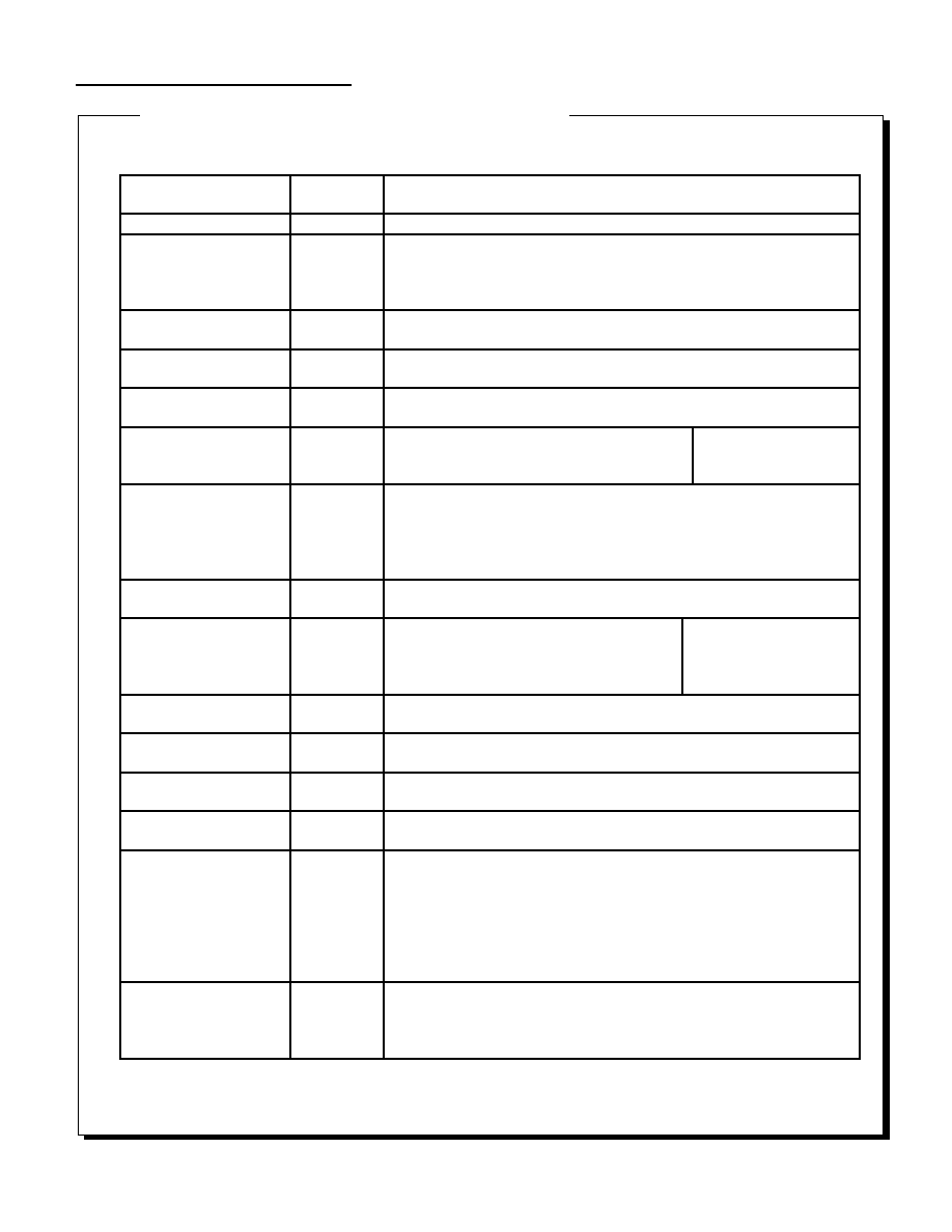
Sound Function
175
Function Reference Supplement
Command Name
Command
Data
Parameter Data
Reserved
00 (hex)
Nothing
Sequence Start
(S--)
01
P1
0-7:
Sequence control number
P2
0-15:
Sequence bank number
P3
0-127:
Sequence song number
P4
0-31: Priority
level
Sequence Stop
(S--)
02
P1
0-7:
Sequence control number
Sequence Pause
(S--)
03
P1
0-7:
Sequence control number
Sequence Continue
(S--)
04
P1
0-7:
Sequence control number
Sequence Volume
(S--)
05
P1
0-7:
Sequence control number
P2
0-127:
Sequence Volume
P3
0-255: Fade
Rate
For details, refer to the
supplement on the fade-in and
fade-out methods.
Tempo Change
(S--)
07
P1
0-7:
Sequence control number
P2
* :
dummy
P3-P4
+32767 -> -32768: Relative tempo value compared to
reference tempo (0000h); 1000h (4296) is double speed,
and -4296 is half speed.
Map Change
(SP-)
08
P1
0-255:
Area number of sound area map being switched
MIDI direct control
(S--)
09
P1 00h-FFh:
MIDI command word
P2
00h-FFh:
MIDI channel word
P3
00h-7Fh:
MIDI data 1
P4
00H-7Fh:
MIDI data 2
For details, refer to the
supplement on the MIDI direct
control bit image.
Volume analize start
(--C)
OA
Nothing (start volume analysis)
Volume analize stop
(--C )
OB
Nothing (stop volume analysis)
DSP stop
( S P C )
OC
Nothing (stop DSP)
Sound all Off
(S P C)
OD
Nothing (stop all sequence slots)
Sequence Pan
(S--)
OE
P1
0-7:
Sequence control number
P2
bit7
0:Control OFF 1 : Control ON
BIT6-0
MIDI PAN data(00h-7Fh)
00h:Left<--->4Oh:Center<-->7Fh:Right
(MIDI PAN consists of 128 steps, but because the SCSP
PAN consists of 32 steps, the two low-order bits of MIDI
PAN data are ignored.)
CD-DA Level
(--C)
80
P1
00h-EOh:CD-DA level Left
8 steps: 00h (off), 20h, 40h,, 60h, 80h, A0h, C0h, and E0h (max.)
P2
00H-EOh:CD-DA level Right
8 steps: 00h (off), 20h, 40h,, 60h, 80h, A0h, C0h, and E0h (max.)
Continued on next page
Table 1. "slSoundRequest" Instruction List
Table 1. "slSoundRequest" Instruction List (continued)
|
Sound Function
176
Continued from previous page
Command Name
Command
Data
Parameter Data
CD-DA Pan
(--C)
81
P1
0-31:
CD-DA pan left, 32 steps
P2
0-31:
CD-DA pan right, 32 steps
Total Volume
(S P C)
82
P1
0-15:
16 steps, 0 is off
Effect Change
(S P C)
83
P1
0-15:
Effect bank number
PCM start
(-P-)
85
P1
bit7
mono 1: stereo
bit6-5
not use
bit4
0:
16bitPCM 1:8bitPCM
bit3-0
0-7:
PCM stream playback number
P2
bit7-5
0-7:
Direct sound Level, 8 steps
bit4-0
0-31:
Direct sound Pan, 32 steps (ignored for Stereo)
P3-P4
0000h-FFFFh:
PCM stream buffer start address (16 high-order
bits of 20-bit data)
P5-P6
0000h-FFFFh;
PCM stream buffer size (number of samples for
one channel)
P7-P8
0000h-FFFFh;
Pitch word (SCSP pitch register data: Oct and
FNS)
P9
bit7-3
0-15:
Effect in select (P9=Rch or MONO)
bit2-0
0-7:
Effect send Level, 8 steps
P10
bit7-3
0-15;
Effect in select (P10=Lch)
bit2-0
0-7:
Effect send Level, 8 steps
PCM stop
(-P-)
86
P1
0-7:
PCM stream playback number for which playback is stopped
Mixer change
(SPC)
87
P1
0-15:
Tone bank number
P2
0-127:
Mixer number
Mixer parameter change
(SPC)
88
P1
0-17
Effect out select
P2
bit7-5
0-7:
Effect return Level, 8 steps
bit4-0
0-31:
Effect Pan, 32 steps
Hard check
(---)
89
P1
0-5:Check item
0 - DRAM 4Mbit read/write
1 - DRAM 8Mbit read/write
2 - SCSP MIDI
3 - sound source output (L/R)
4 - sound source output (L)
5 - sound source output (R)
PCM parameter change
(-P-)
8A
P1
0-7:
PCM stream playback number
P2
bit7-5
0-7:
Direct sound Level, 8 steps
bit4-0
0-31:
Direct sound Pan, 32 steps
P3-04
0000h-FFFFh:
pitch word
P5
bit7-3
0-15:
Effect in select (P5=Rch or MONO)
bit2-0
0-7:
Effect send Level, 8 steps
P6
bit7-3
0-15:
Effect in select
(P6=Lch)
bit2-0
0-7:
Effect send Level, 8 steps
Reserved
8B-FF
Nothing
(SPC)
S:
Command that acts on Sequence playback, or that concerns Sequence playback
P:
Command that acts on PCM stream playback, or that concerns PCM stream playback
C:
Command that acts on CD-DA playback, or that concerns CD-DA playback
|
Sound Function
177
MIDI direct control bit image
Fade in method
Issue the sequence volume command before issuing the start command. The sound fades in from Volume = 0 to
the specified sequence volume at the specified fade rate. The fade-in curve can be controlled as desired by
using the sequence volume command twice or more.
Fade out method
Issue the sequence volume command with Volume = 0. The sound fades out from the current sequence volume
to Volume = 0 at the specified fade rate. The fade-out curve can be controlled as desired by using the sequence
volume command twice or more.
Note 1:
Because commands such as "MIDI direct control" are closely affected by the relationship between the MIDI
channel and tone and the usage of the DSP program and mixer, work in close cooperation with the sound
developer.
Note 2:
Because a specialized DSP program is required in order to analyze each frequency band with the Volume
Analyze function, use the Effect Change command to download the DSP program before issuing the Volume
Analyze command. The DSP program is not needed in the case of the main volume. In addition, because the
data is updated at 16msec intervals when executing Volume Analyze, the volume data should be read at 16msec
intervals or more.
Note 3:
When "stereo" is specified at PCM start, the first half of the data in the area specified by P3-P4 is processed as
the right channel data, and the second half is processed as the left channel data. The PCM stream buffer must
be set so that it starts from an even address and is an even number of bytes in size. The PCM stream buffer start
address is specified by the high-order 16 bits of 20-bit data, so the four low-order bits are always "0". The P7-P8
pitch word specifies the SCSP pitch register word octave + F number as is. For details on pitch, refer to the SCSP
manual.
Note 4:
Because the sound CPU does not operate while the PCM stream playback data is being transferred (from the
host to sound memory), operation is not guaranteed if music or sound effects are played simultaneously while
data is transferred continuously for an extended period of time. Either use DMA burst writes, or conduct the DMA
transfer in intervals.
Note 5:
Because the PCM stream playback rate can place a high demand on data transfer capabilities, in some cases not
all eight "voices" will be played back. guidelines are indicated for your reference in the item entitled "Demands of
data transfer."
Priority level
: 0 - 31
Sound priority ranking at sequence
start
CMD
: 0 - 7
MIDI command 8 - F (8 - F -> 0 - 7)
KNo
: 0 - 7
Sound control number
MIDI Ch
: 0 - 31
MIDI channel
MIDI Data #1
: 0 - 127
MIDI data byte #1
MIDI Data #2
: 0 - 127
MIDI data byte #2
7
6
5
4
3
2
1
0
0
Priority level
CMD
1
KNo
MIDI Ch
2
MIDI Data #1
3
MIDI Data #2
|

Sound Function
178
void
slWaitSound
Wait for function execution by sound driver
Format
void slWaitSound(Addr)
void *Addr
Parameters
Addr
Byte-type address
Function
This function waits until the data in the specified address is "0". This function
indicates that the sound driver executed a function.
Return Value
None
Remarks
Example of usage:
slWaitSound(slSndMapChange(0)); /* Wait for current map to be switched */
Refer to: Chapter 14, "Sound Library"
slWaitSound
|
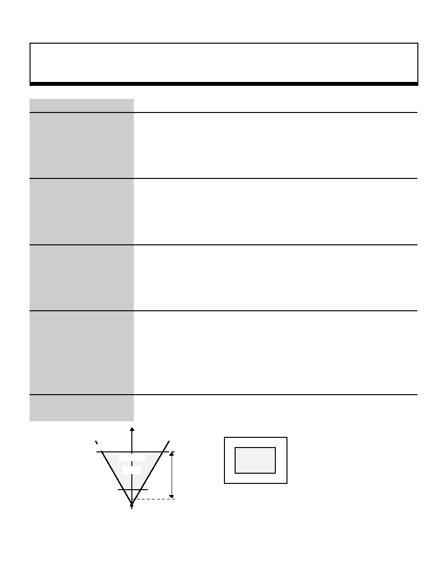
Miscellaneous Function
179
FIXED
slCheckOnScreen
Determine whether specified coordinates are within viewing area
Format
FIXED slCheckOnScreen(pos , size)
FIXED *pos ;
FIXED size ;
Parameters
pos[XYZ]
XYZ coordinate values of object position
size
Object size
Function
This function converts the specified object position through the current matrix,
tests whether or not an object of the specified size at that position would be
displayed on the screen or not, and returns the result.
Return Value
When extending beyond the display area in the Z direction: -1 (FFFFFFFF)
When extending beyond the display area to the left, right, top, or bottom: -2
(FFFFFFFE)
When contained within the screen: Z_position
Remarks
The following diagrams illustrate the relationship between the display area and the
return value.
Refer to:
slCheckOnScreen
Direction of line of sight
Rear boundary surface
Display area
R-Z_pos
R= -2
R= -2
R= -2
R= -2
R= -2
R= -2
R= -1
Front boundary surface
Zlimit
Display area
Projection surface
Note: "R="indicates the return value generated
by the function "slCheckOnScreen".
Viewpoint
|

Miscellaneous Function
180
void
slDMACopy
Block transfer using CPU DMA
Format
void slDMACopy(src , dst , cnt)
void*src ;
void*dst ;
Uint32 cnt ;
Parameters
src
Starting address of source memory area
dst
Starting address of destination memory area
cnt
Block transfer amount (bytes)
Function
This function performs a block transfer using the CPU's DMA function. For the
"cnt" parameter, specify how many bytes are to be transferred.
When a transfer is made to a cache area, this function initializes the cache.
Return Value
None
Remarks
The function "slDMACopy" terminates soon after DMA is initiated. To wait until the
transfer is completed, use the function "slDMAWait". If another DMA transfer has
already been initiated, the function "slDMACopy" waits until the other transfer
terminates before initiating a new DMA transfer.
Refer to: Chapter 9, "Controller Input"
slDMACopy
|
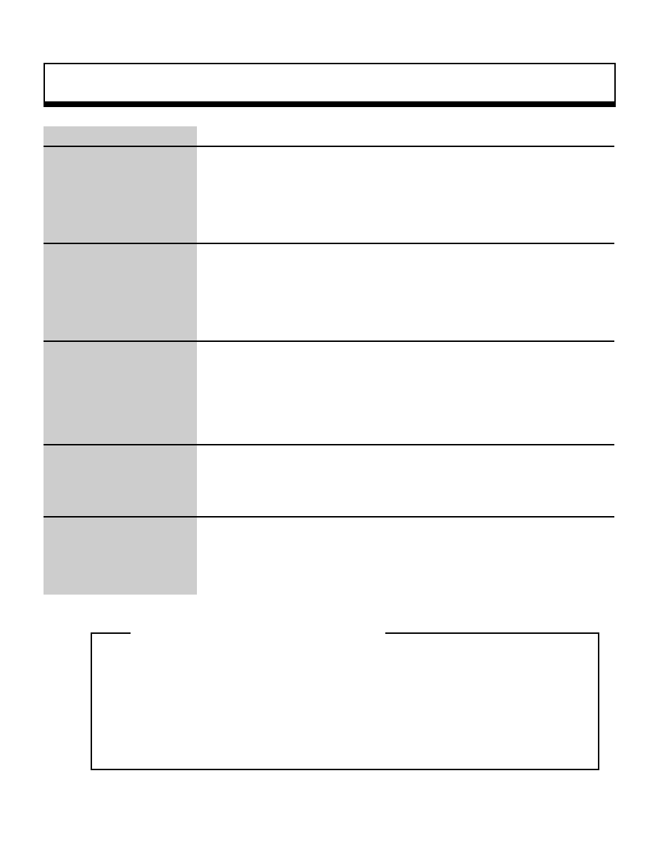
Miscellaneous Function
181
void
slDMAWait
Wait until termination of DMA transfer
Format
void slDMAWait(void)
Parameters
None
Function
This function waits until a DMA transfer initiated by the function "slDMACopy"
terminates.
Return Value
None
Remarks
The function "slDMACopy" always uses the same channel, and if a transfer is in
progress, the function waits until the first transfer terminates before initiating the
new one. As a result, the user can execute consecutive DMA transfers without
needing to be conscious of the completion of the transfers. An example is shown
below.
siDMACopy(src0 , dst0 , cnt0);
/* first transfer request */
siDMACopy(src1 , dst1 , cnt1);
/* second transfer request (execute after termination of first transfer
* /
siDMACopy(src2 , dst2 , cnt2);
/* third transfer request (execute after termination of second transfer
* /
siDMAwait(void) ;
/* wait for termination of third transfer */
Refer to: Chapter 9, "Controller Input"
slDMAWait
_oe
Consecutive execution of DMA transfers
_oe
|

Miscellaneous Function
182
void
slInitSynch
Wait for V-BLANK and synchronize event processing with screen
Format
void slInitSynch()
Parameters
None
Function
This function waits for V-BLANK and synchronizes event processing with the
screen.
Return Value
None
Remarks
Also refer to the function "slSynch".
Refer to: HARDWARE MANUAL vol. 2 (VDP2"
slInitSynch
|
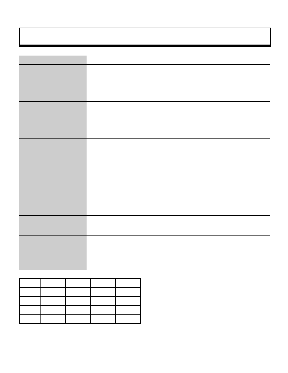
Miscellaneous Function
183
void
slInitSystem
SGL system initialization
Format
void slInitSystem(tv_mode , texadr , cnt)
Uint16tv_mode ;
TEXTURE*texadr ;
Uint16 cnt ;
Parameters
tv_mode
Screen mode specification
texadr Starting address of memory area where texture data is stored
cnt
Graphics processing unit specification
Function
This function initializes the SGL system.
For the parameters, respectively, substitute the #define value indicating the
screen mode, the starting address of the memory area where the texture
information table was stored, and the number of V-blanks indicating the graphics
processing unit.
1 V-BLANK is 1/60 of a second if non-interlaced and 1/30 of a second if double-
interlaced; the graphics processing unit is a multiple of this value.
For the screen mode specification, substitute the values shown below.
Return Value
None
Remarks
Initialization includes slave CPU initialization, matrix buffer initialization, scroll data
initialization, etc.
For details on the values initialized by the function "slInitSystem", refer to the list of
default values set by "slInitSystem" at the end of the function reference.
Resolution
320(H)
352(H)
640(H)
704(H)
224(V)
TV_320x224
TV_352x224
TV_640x224
TV_704x224
240(V)
TV_320x240
TV_352x240
TV_640x240
TV_704x240
448(V)
TV_320x448
TV_352x448
TV_640x448
TV_704x448
480(V)
TV_320x480
TV_352x480
TV_640x480
TV_704x480
Note: The values in the above table are defined in "sl_def.h", provided with the system
.
Refer to: Chapter 8, "Scrolls""
slInitSystem
¥As shown in the examples in the table at left, the
screen mode specification is defined as a macro in the
form TV_horizontal x vertical (pixels), according to the
resolution of the screen mode.
|

Miscellaneous Function
184
void
slIntFunction
Register function to be executed during blanking
Format
void slIntFunction(func)
void(*func)() ;
Parameters
func
Starting address of function to be registered
Function
This function registers a function to be executed during blanking.
Return Value
None
Remarks
The only functions that can be registered are void-type with no parameters.
void<function name>(void);
Refer to:
slIntFunction
|
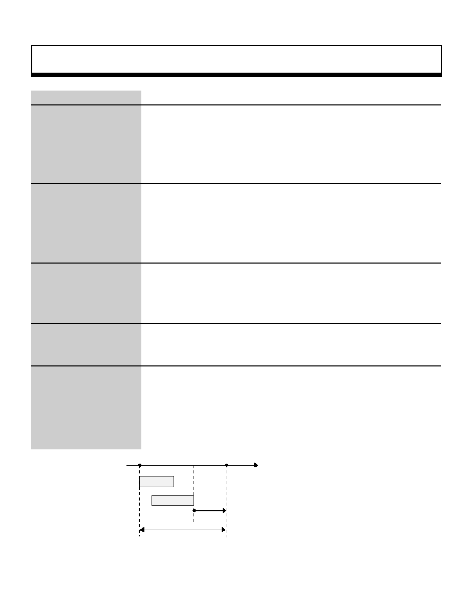
Miscellaneous Function
185
void
slSynch
Synchronization with event processing unit time
Format
void slSynch()
Parameters
None
Function
This function waits until the event processing unit time is reached.
Return Value
None
Remarks
Screen switching (display), etc., is performed in the graphics processing units
specified by the function "slInitSystem".
The graphics processing unit is displayed in terms of the number of V-blanks. 1
blank is 1/60 of a second if non-interlaced and 1/30 of a second if double-
interlaced. Refer to the function "slInitSystem" for further details.
Refer to: Chapter 8, "Scrolls"
slSynch
V-BLANK
V-BLANK
time
Data transfer
Event processing
slSynch
Event processing unit time
|
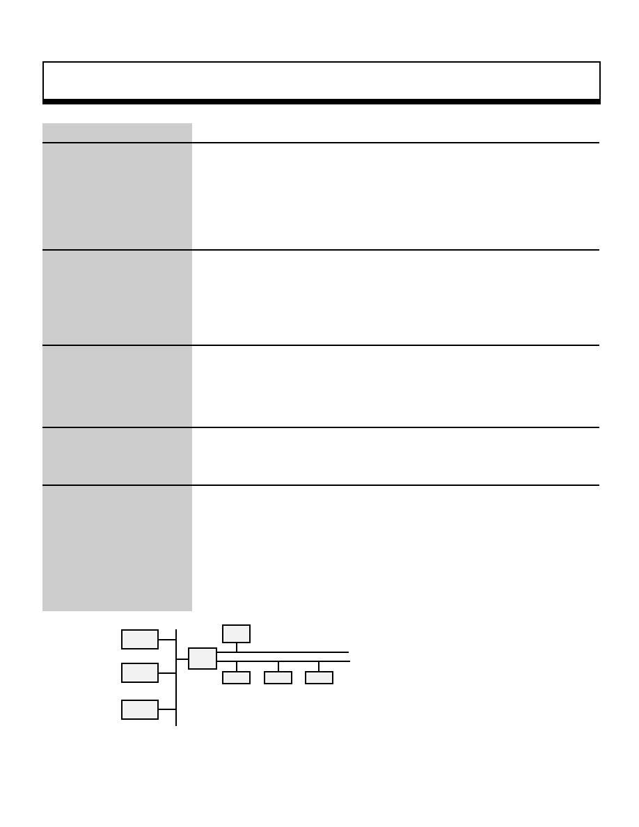
Miscellaneous Function
186
Bool
slTransferEntry
Data transfer request during blanking
Format
void slTranferEntry(str , dst , size)
void*str ;
void*dst ;
Uint16 size ;
Parameters
str
Starting address of transfer source
dst
Starting address of transfer destination
size
Data transfer amount (bytes)
Function
This function transfers data during V_BLANK. For the parameter "size", specify
how many bytes of data are to be transferred.
Return Value
None
Remarks
In order to do a data transfer using the indirect mode of the DMA in the SCU, the
data transfer cannot be made over the same bus.
For details, refer to the chapter on the SCU in the HARDWARE MANUAL vol. 1.
The diagram below is a conceptual model of the bus.
Refer to:
slTransferEntry
void
CPU Bus
A-Bus
B-Bus
CPU
WorkRAM
Low
WorkRAM
High
CD
Buffer
SCU
VDP1
VDP2
SCSP
Data transfer cannot be performed over the same bus.
Note: Transfers from work RAM-high to ork RAM-low are not possible.
Data transfers from work RAM-high to VDP1 are possible.
|

Miscellaneous Function
187
slSetTrayCheck
CD tray open check
Format
void slSetTrayCheck(flag)
Uint8 flag
Parameters
flag
ON or OFF
Function
This function specifies whether or not to perform a check in order to shift to the
multiplayer screen when the CD tray is open.
Specify the flag as either ON or OFF.
When this function is called, the status is cleared; therefore, if the tray is already
open when the flag is set to ON, the check will not be made until the next time the
tray is opened.
Return Value
None
Remarks
Refer to:
slSetTrayCheck
void
|

Miscellaneous Function
188
slChashePurge
Cache purge
Format
void shChashePurge()
Parameters
None
Function
This function initializes the cache data in the CPU. This function is used when the
cache area is changed by a DMA transfer, etc.
Return Value
None
Remarks
Refer to:
slChashePurge
Bool
|

Miscellaneous Function
189
slDMAStatus
DMA transfer check
Format
void slDMAStatus()
Parameters
None
Function
This function checks whether or not a DMA transfer initiated by the "slDMACopy()"
function or the "slDMAXCopy()" function is in progress or not, and returns a flag.
If the transfer is in progress, this function returns "ON"; if not, this function returns
"OFF".
Return Value
None
Remarks
Refer to:
slDMAStatus
|

SGL Reference
Structure Reference
This section introduces structures, variable types and macros that are unique
to the SGL. These are essential to programming with the SGL, and the
defined contents of each are also important.
Study this reference in addition to the Function Reference.
|

Structure
1
ATTR
Face attribute list
Structure:
typedef struct {
Uint8 flag ;
Uint8 sort ;
Uint16 texno ;
Uint16 atrb ;
Uint16 colno ;
Uint16 gstb
Uint16 dir ;
} ATTR ;
Members:
flag
Front/back setting
sort
Sort setting
texno
Texture number
atrb
Attribute data
colno
Color number
gstb
Gouraud setting
dir
Texture reversal setting and type
Description:
This structure defines the polygon face attribute list.
Remarks:
for details on the face attributes and how to use them, refer to chapter 7,
"Polygon Face Attributes," in the Programmer's Tutorials.
Refer to: Chapter 2, "Graphics"
ATTR
|

Structure
2
EVENT
Event management
Structure:
typedef struct evnt {
WORK *work ;
struct event *next ;
struct event *before ;
void (*exad)() ;
Uint8 user[EVENT_SIZE-(sizeof(WORK*)
+sizeof(struct evnt*)*2+sizeof(void (*)()))]
}EVENT;
Members:
work
Work area pointer
next
Starting address of next event
before Starting address of previous event
(exad)() Function execution address
user[]
Work area
Description:
This structure defines the event management table. Set the address received
from the library function "slGetWork" in the member "work".
The default value is NULL.
Remarks
"EVENT_SIZE" in the member "user[]" is 128 bytes. As a result, the user area is
112 bytes.
Refer to: Chapter 10, "Event Control"
EVENT
|

Structure
3
PDATA
Polygon model data
Structure
typedef struct {
POINT *pntb1 ;
Uint32 nbPoint ;
POLYGON *pltb1 ;
Uint32 nbPolygon ;
ATTR *attb1 ;
} PDATA ;
Members
pntb1
Vertex list pointer
nbPoint Number of vertices
pltb1
Face list pointer
nbPolygon
Number of faces
attb1
Attribute list pointer
Description:
This structure defines the polygon model data.
Remarks
Refer to: Chapter 2, "Graphics"
PDATA
|

Structure
4
PICTURE
Texture registration table
Stracture
typedef struct {
Unit16 texno ;
Unit16 cmode ;
void *pcsrc ;
} PICTURE ;
Members
texno
Texture number
cmode Color mode
pcsrc
Starting address of texture data to be registered
Description
This structure is the information table for transferring and registering texture data
within VRAM.
Remarks
Refer to the textures in the "Polygon Face Attributes.
Refer to: Chapter 7, "Polygon Face Attributes"
PICTURE
|

Structure
5
POLYGON
Polygon face list
STRUCTURE
typedef struct {
VECTOR norm ;
Uint16 Vertices[4] ;
} POLYGON ;
Members
norm
Normal vector
Vertices[4]
Vertex number list
Description
This structure defines the polygon face list
Remarks
Refer to: Chapter 2, "Graphics"
POLYGON
|
Structure
6
ROTSCROLL
Rotation parameters
STRUCTURE
typdef struct {
FIXED XST ;
FIXED YST ;
FIXED ZST ;
FIXED DXST :
FIXED DYST ;
FIXED DX ;
FIXED DY ;
FIXED MATA ;
FIXED MATB ;
FIXED MATC ;
FIXED MATD ;
FIXED MATE ;
FIXED MATF ;
Sint16 PX ;
Sint16 PY ;
Sint16 pZ ;
Sint16 dummy0 ;
Sint16 CX ;
Sint16 CY ;
Sint16 CZ ;
Sint 16 dummy1 ;
FIXED MX ;
FIXED MY ;
FIXED KX ;
FIXED KY ;
Uint32 KAST ;
Sint32 DKA ;
}ROTSCRLL ;
Members
XST
Scroll screen start coordinate Xst
YST
Scroll screen start coordinate Yst
ZST
Scroll screen start coordinate Zst
DXST
Scroll screen vertical direction coordinate increment amount dXst
DYST
Scroll screen vertical direction coordinate increment amount dYst
DX
Scroll screen horizontal direction coordinate increment amount dX
DY
Scroll screen horizontal direction coordinate increment amount dY
MATA Rotating matrix parameter A
MATB Rotating matrix parameter B
MATC Rotating matrix parameter C
MATD Rotating matrix parameter D
MATE Rotating matrix parameter E
MATF
Rotating matrix parameter F
PX
Viewpoint coordinate Px
PY
Viewpoint coordinate Py
PZ
Viewpoint coordinate Pz
dummy0
Dummy area
CX
Center coordinate Px
CY
Center coordinate Py
|
Structure
7
CZ
Center coordinate Pz
dummy1
Dummy area
MX
Parallel movement amount Mx
MY
Parallel movement amount My
KX
Enlargement/reduction coefficient kx
KY
Enlargement/reduction coefficient ky
KAST
Coefficient table start address KAst
DKAST Coefficient table vertical direction address increment DKAst
DKA
Coefficient table vertical direction address increment DKA
Description
This structure defines the rotation parameter table.
The rotation parameter table is read for each line of the rotating scroll screen, and
the screen is displayed according to those values.
Remarks
Used together with the NORMAL macro, this macro is used to make the
POLYGON face list.
Refer to:
ROTSCROLL
|

Structure
8
SPR_ATTR
Sprite attributes table
STRUCTURE
typedef struct spratr {
Uint16 texno ;
Uint16 atrb ;
Uint16 colno ;
Uint16 gstb ;
Uint16 dir ;
} SPR_ATTR ;
Members
texno
Texture number
atrb
Attribute data (display mode)
colno
Color number
gstb
Gouraud shading table
dir
Texture reversal
Description
This structure is the parameter table for sprite display. Basically, these parameters
conform with the texture parameters.
Remarks
Refer to the group of functions concerning sprite display.
Refer to:
SPR_ATTR
|

Structure
9
SPRITE
Sprite data
STRUCTURE
typedef struct {
Uint16 CTRL ;
Uint16 LINK ;
Uint16 PMOD ;
Uint16 COLR ;
Uint16 SRCA ;
Uint16 SIZE ;
Uint16 XA ;
Uint16 YA ;
Uint16 XB ;
Uint16 YB ;
Uint16 XC ;
Uint16 YC ;
Uint16 XD ;
Uint16 YD ;
Uint16 GRDA ;
Uint16 DMMY ;
} SPRITE ;
Members
CTRL
Control function
LINK
Link address
PMOD Put mode
COLR Color data
SRCA CG address
SIZE
Character size
XA
X coordinate of display position A
YA
Y coordinate of display position A
XB
X coordinate of display position B
YB
Y coordinate of display position B
XC
X coordinate of display position C
YC
Y coordinate of display position C
XD
X coordinate of display position D
YD
Y coordinate of display position D
GRDA Gouraud shading table
DMMY Dummy data used to match up with size
Description
This data type is used to directly pass data to the VDP1, and is the data table
used to display sprites.
Sprite picture data must be stored and registered in VRAM beforehand. (The
same is true for texture data and scroll data.) For details, refer to the textures in
"Polygon
Face Attributes".
Remarks
Textures and sprites used in the Sega Saturn system have very similar data
structures, but their display methods differ as follows:
Textures are applied to polygon faces and displayed.
Sprites are displayed independently.
Refer to: Chapter 7, "Polygon Face Attributes"
SPRITE
|
Structure
10
TEXTURE
Texture data
STRUCTURE
typedef struct {
Uint16 Hsize ;
Uint16 Vsize ;
Uint16 CGadr ;
Uint16 HVsize ;
} TEXTURE ;
Members
Hsize
Horizontal size of texture
Vsize
Vertical size of texture
CGadr CG address of texture/8
HVsize Horizontal size/8, vertical size (for hardware) ((HSIZE/8)<<8)|(V SIZE)
Description
This structure is the texture management table that is needed in order to use
textures in the SGL.
Remarks
For details, refer to chapter 7, "Polygon Face Attributes",in the Programmer's
Tutorial.
Refer to: Chapter 7, "P
TEXTURE
|

Structure
11
WORK
Work area management
STRUCTURE
typedef struct work {
struct work *next ;
Uint8 user[WORK_SIZE-sizeof(struct work *)] ;
} WORK ;
Members
next
Pointer to next work area
user[]
Free area within the work area that the user can use
Description
This structure indicates a work area that can be used within an event. The
member "user" consists of the work size (WORK_SIZE = 64 bytes) less the size of
the member "next" (4 bytes), for a total of 60 bytes.
For details, refer to the Chapter 10, "Event Control" in the Programmer's Tutorial.
Remarks
Refer to: Chapter 10, "Event Control"
WORK
|

Structure
12
SmpcDateTime
RTC time
STRUCTURE
typedef
struct
{
Uint16 year :
Uint8
month ;
Uint8
date :
Uint8
hour ;
Uint8
minute ;
Uint8
second ;
} SmpcDateTime ;
Members
year
Year
month Day of the week and month
date
Date
hour
Hours
minute Minutes
second Seconds
Description
This structure is used to reference the RTC time.
Remarks
Use this structure when referencing the "rtc" member of the system variable
"Smpc_Status".
Refer to: HARDWARE MANUAL vol. 1 (SMPC)
SmpcDateTime
|

Structure
13
SmpcStatus
SMPC status
STRUCTURE
typedef
struct {
Uint8
cond ;
SmpcDateTime month ;
Uint8
ctg :
Uint8
area ;
Uint16
system ;
Uint32
smem ;
} SmpcStatus ;
Members
cond
Status
rtc
RTC time
ctg
Cartridge code
area
Area code
system System status
smem
SMPC memory data
Description
This structure is used to reference the SMPC system status.
Remarks
Use this structure when referencing the system variable "Smpc_Status".
The member "rtc" can be referenced as the structure "SmpcDateTime".
Special get and set functions are provided for the member "smem".
Refer to: HARDWARE MANUAL vol. 1 (SMPC)
SmpcStatus
|

Structure
14
PerDigital
Digital device
STRUCTURE
typedef
struct {
Uint8
id ;
Uint8
ext :
Uint16
data ;
Uint16
push ;
Uint16
pull ;
} PerDigital ;
Members
id
Peripheral ID
ext
Extended data size
data
Current button data
push
Depressed button data
pull
Unpressed button data
Description
This structure is used to reference digital devices.
Remarks
Use this structure when referencing the system variable "Smpc_Peripheral". All
devices can be handled as digital devices.
Refer to: HARDWARE MANUAL vol. 1 (SMPC)
PerDigital
|

Structure
15
PerAnalog
Analog device
STRUCTURE
typedef
struct {
Uint8
id ;
Uint8
ext :
Uint16
data ;
Uint16
push ;
Uint16
pull ;
Uint8
x ;
Uint8
y ;
Uint8
z ;
} PerAnalog ;
Members
id
Peripheral ID
ext
Extended data size
data
Current button data
push
Depressed button data
pull
Unpressed button data
x
Absolute value of X axis data
y
Absolute value of Y axis data
z
Absolute value of Z axis data
Description
This structure is used to reference analog devices.
Remarks
Type-cast the system variable "Smpc_Peripheral" and use this structure to
reference a peripheral as an analog device.
Refer to: HARDWARE MANUAL vol. 1 (SMPC)
PerAnalog
|

Structure
16
PerPoint
Pointing device
STRUCTURE
typedef
struct {
Uint8
id ;
Uint8
ext :
Uint16
data ;
Uint16
push ;
Uint16
pull ;
Uint16
x ;
Uint16
y :
} PerPoint ;
Members
id
Peripheral ID
ext
Extended data size
data
Current button data
push
Depressed button data
pull
Unpressed button data
x
X coordinate
y
Y coordinate
Description
This structure is used to reference a pointing device.
Remarks
Type-cast the system variable "Smpc_Peripheral" and use this structure to
reference a peripheral as a pointing device.
Refer to: HARDWARE MANUAL vol. 1 (SMPC)
PerPoint
|

Structure
17
PerKeyBoard
Keyboard device
STRUCTURE
typedef
struct {
Uint8
id ;
Uint8
ext :
Uint16
data ;
Uint16
push ;
Uint16
pull ;
Uint8
cond ;
Uint8
code ;
} PerKeyBoard ;
Members
id
Peripheral ID
ext
Extended data size
data
Current button data
push
Depressed button data
pull
Unpressed button data
cond
Status data
code
Key code
Description
This structure is used to reference the keyboard device.
Remarks
Type-cast the system variable "Smpc_Peripheral" and use this structure to
reference a peripheral as a keyboard device.
Refer to: HARDWARE MANUAL vol. 1 (SMPC)
PerKeyBoard
|
Variable Type
18
ANGLE
Angle data variable type
Structure
typedef Sint16 ANGLE ;
Members
Description
Angle data notation variable type.
The range from 0¡ to 359¡ is expressed by 0x0000 to 0xffff.
Remarks
Refer to: : Chapter 1, "Sega Graphics Library"
ANGLE
|

Variable Type
19
FIXED
Fixed-point decimal variable type
Structure
typedef Sint32 FIXED ;
Members
Description
This variable type indicates fixed-point decimal data. FIXED-type values are
represented in the following manner.
High-order 16 bits: Integer portion
Low-order 16 bits: Decimal portion
Ex,: 16.5 -> 0x00108000
Remarks
Refer to: Chapter 1 "Sega Graphics Library"
FIXED
|

Variable Type
20
MATRIX
Matrix variable type
Structure
typedef FIXED MATRIX[4][3] ;
Members
Description
Matrix notation variable type
Remarks
FIXED matrix [4][3];
MATRIX matrix;
The two definitions shown above have the same meaning.
Refer to: Chapter 5, "Matrices"
MATRIX
|

Variable Type
21
POINT
Vertex data type
Structure
typedef FIXED POINT[xyz] ;
Members
Description
This variable type defines the vertex data used in polygons.
Remarks
FIXED point [xyz];
FIXED point [3];
POINT point;
All three of the above definitions have the same meaning.
Refer to: Chapter 2, "Graphics"
POINT
|

Variable Type
22
TEXDAT
Texture data variable type
Structure
typedef UINT16 TEXDAT ;
Members
Description
This variable type is used to define the actual texture itself.
Remarks
Refer to: Chapter 7, "Polygon Face Attributes"
TEXDAT
|

Variable Type
23
VECTOR
Vector variable type
Structure
TYPED FIXED VECTOR[XYZ}
Members
Description
Vector data variable type
Remarks
FIXED vector[XYZ];
FIXED vector[3];
VECTOR vector
The above three definitions all have the same meaning.
Refer to:
VECTOR
|

MACRO
24
ATTRIBUTE
Polygon attribute specification
Structure
#define ATTRIBUTE(plane,sort,texture,color,gourand,mode,dir,option)
_@_@_@_@ {
plane,(sort)|(((dir)>>16)&0x01c)|(option),__
texture,(mode)|(((dir)>>24)&0xc0,color__
gourud,(dir)&0x03f
}
Uint8 plane ;
Uint8 sort ;
Uint16 texture ;
Uint16 color ;
Uint16 gouraud ;
Uint 16 mode ;
Uint 32 dir ;
Uint16 option :
Members
plane
Front/back attribute
sort
Z sort specification
texture Texture number, or No_Texture
color
C_RGB macro-specified color, color palette number, or No_Palet
gouraud
Gouraud table, or No_Gouraud
mode
Various mode specifications for the polygon
dir
Specification of texture display direction, etc.
option Other settings for the polygon
Description
This macro sets the
face attributes (particularly the polygon
front
face)
concerning polygon drawing. For details on the meaning of and substitution
values for each parameter, refer to chapter 7, "Polygon Face Attributes," in the
Programmer's Tutorial. Also refer to the list of ATTRIBUTE macro substitution
values at the end of the Structure Reference.
Remarks
When using texture, the member color is sometimes used to specify the color
bank number.
Refer to: Chapter 7, "Polygon Face Attributes"
ATTRIBUTE
|

MACRO
25
C_RGB
RGB value specification
Structure
#define C_RGB(r,g,b) (((b)&0x1f)<<10|(g)&0x1f)<<5|((r)&0x1f) |0x8000)
Uint8r ;
Uint8 g ;
Uint8 b ;
Members
r
Red
g
Green
b
Blue
Description
This macro specifies the RGB values used to represent color gradations. The
color gradation values can range from 0 to 1f for each of red, green, and blue.
Remarks
This macro cannot be used to specify the transparent color.
Refer to: Chapter 7, "Polygon Face Attributes"
C_RGB
|

MACRO
26
DEGtoANG
Angle conversion macro
Structure
#define DEGtoANG(d) (ANGLE)((d)*65536.0/360.0))
float d ;
Members
d
Angle to be converted (DEG notation)
Description
This macro converts a floating-point angle value expressed in DEG notation to
an ANGLE-type value.
Remarks
Refer to: Chapter 1, "Sega Graphics Library"
DEGtoANG
|

MACRO
27
NORMAL
Coordinate value conversion macro
Structure
#define NORMAL(x,y,z) {POStoFIXED(x,y,z)
Members
x
X coordinate to be converted
y
Y coordinate to be converted
z
Z coordinate to be converted
Description
This macro converts a normal vector XYZ coordinates expressed by floating-
point decimals into FIXED-type variables.
Remarks
Used together with the VERTICES macro, this macro is used to make the
POLYGON face list.
Refer to:
NORMAL
|

MACRO
28
PICDEF
Texture management table
Structure
#define PICDEF(texno,cmode,pcsrc) {(Uint16)(texno),(Uint16)(cmde),
(void*)(pcsrc)}
Uint16 texno ;
Uint16 cmode ;
void*pcsrc ;
Members
texno
Texture number
cmode Color mode (COL_16, 64, 128, 256, or 32K)
pcsrc
Pointer for texture data defined by "TEXDAT"
Description
This macro creates the table of information used to set a texture in VRAM so that
the texture can be handled within a program.
Remarks
Refer to: Chapter 7, "Polygon Face Attributes"
PICDEF
|

MACRO
29
POStoFIXED
Coordinate value conversion macro
Structure
#define POStoFIXED(x,y,z) {toFIXED(x),(toFIXED(y),toFIXED(z)}
Members
x
X coordinate to be converted
y
Y coordinate to be converted
z
Z coordinate to be converted
Description
This macro converts the XYZ coordinate values to FIXED-type variables.
Remarks
Refer to: Chapter 1, "Sega Graphics Library"
POStoFIXED
|

MACRO
30
TEXDEF
Texture registration table
Structure
#define TEXDEF(h, v,presize) (h,v,(((cgaddress+(presize))*4)>>pal)/8,
(((h)&0x1f8)<<5|(v))}
Uint16h ;
Uint16v ;
Uint32 presize ;
Members
h
Horizontal size of texture
v
Vertical size of texture
presize Previously registered texture size (vertical x horizontal)
Description
This macro creates a table for getting texture information.
Remarks
Reference macros
#define cgaddress 0x10000
#define pal COL_32K
Refer to: Chapter 7, "Polygon Face Attributes"
TEXDEF
|

MACRO
31
toFIXED
Value conversion macro
Structure
#define toFIXED(a) ((FIXED)((a)*65536.0)
Members
a
Value to be converted
Description
This macro converts the value supplied as the parameter into a FIXED-type
value.
Remarks
Refer to: Chapter 1, "Sega Graphics Library"
toFIXED
|

MACRO
32
VERTICES
Polygon vertex variable string
Structure
#define VERTICES(v0, v1, v2, v3) (v0, v1, v2, v3}}
Uint16 v0 ;
Uint16 v1 ;
Uint16 v2 ;
Uint16 v3 ;
Members
v0
Vertex v0
v1
Vertex v1
v2
Vertex v2
v3
Vertex v3
Description
This macro specifies the polygon vertex numbers expressed as integers.
Remarks
Used together with the NORMAL macro, this macro is used to make the polygon
face list.
Refer to: Chapter 2, "Graphics"
VERTICES
|

SGL Reference
Appendix
This appendix contains supplementary tables for the
Function Reference and for the Structure Reference.
|
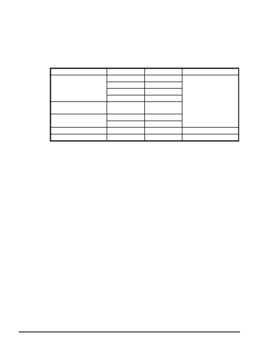
2
1. Default settings when the function "slInitSystem" is executed
In the SGL, when the function "slInitSystem" is executed, in addition to initializing various
types of memory and system variables, the following default settings are made.
When the system is initialized, the default window is set up.
Table 1-1. Default Window Specs
Setting
Parameter
Setting
Function used to reset
Window coordinates
Left
0
slWindow
Top
0
Right
ScreenXSize - 1
Bottom
ScreenYSize - 1
Rear boundary surface
specification
Zlimit
0x7fff
Vanishing point
CenterX
ScreenXSize / 2
CenterY
ScreenYSize / 2
Perspective angle
PersAngle
90
°
slPerspective
Display level
ZdspLevel
1
slZdspLevel
ScreenXSize = Resolution (in pixels) in horizontal direction for screen mode
ScreenYSize = Resolution (in pixels) in vertical direction for screen mode
|
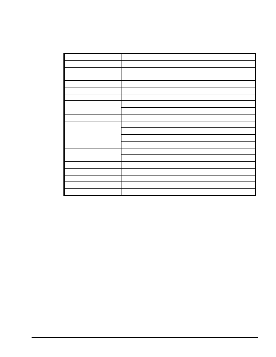
3
2) Scroll settings
When the system is initialized, the scrolls are set up as follows.
Table. Scroll Default Settings
Setting
Contents of setting
Scroll screens displayed
NBG0, NBG1, RBG0
Priority
NBG0 > SPR0 > SPR1 > RBG0 > NBG1 > NBG2 > NBG3
7
6
5
4
3
2
1
Number of scroll colors
256 colors on each screen
Color RAM mode
1 (2048 colors out of 32,768 colors)
VRAM partitions
Both banks A and B partitioned
Character data
NBG0, NBG1: 25E60000 -
RBG0 : 25E00000 -
Character size
8 x 8 dots on each screen
Pattern name data
NBG0 : 25E76000 and up
NBG1 : 25E78000 and up
RBG0: 25E40000 and up (rotation parameters A)
RBG0: 25E50000 and up (rotation parameters B)
Pattern name size
NBG0: 1 word, 10 bits with reversal function for each cell
NBG1, RBG0: 1 words, 12 bits with no reversal function
Plane size
64 x 64 cells on each screen
Background screen color
Black at 25E3FFFE (R = 0, G = 0, B = 0)
Rotation parameters
25E3FF00 and up
Sprite data
Mixture of palette and RGB format
Special effects functions
Mosaic, color offset, etc., not used
|
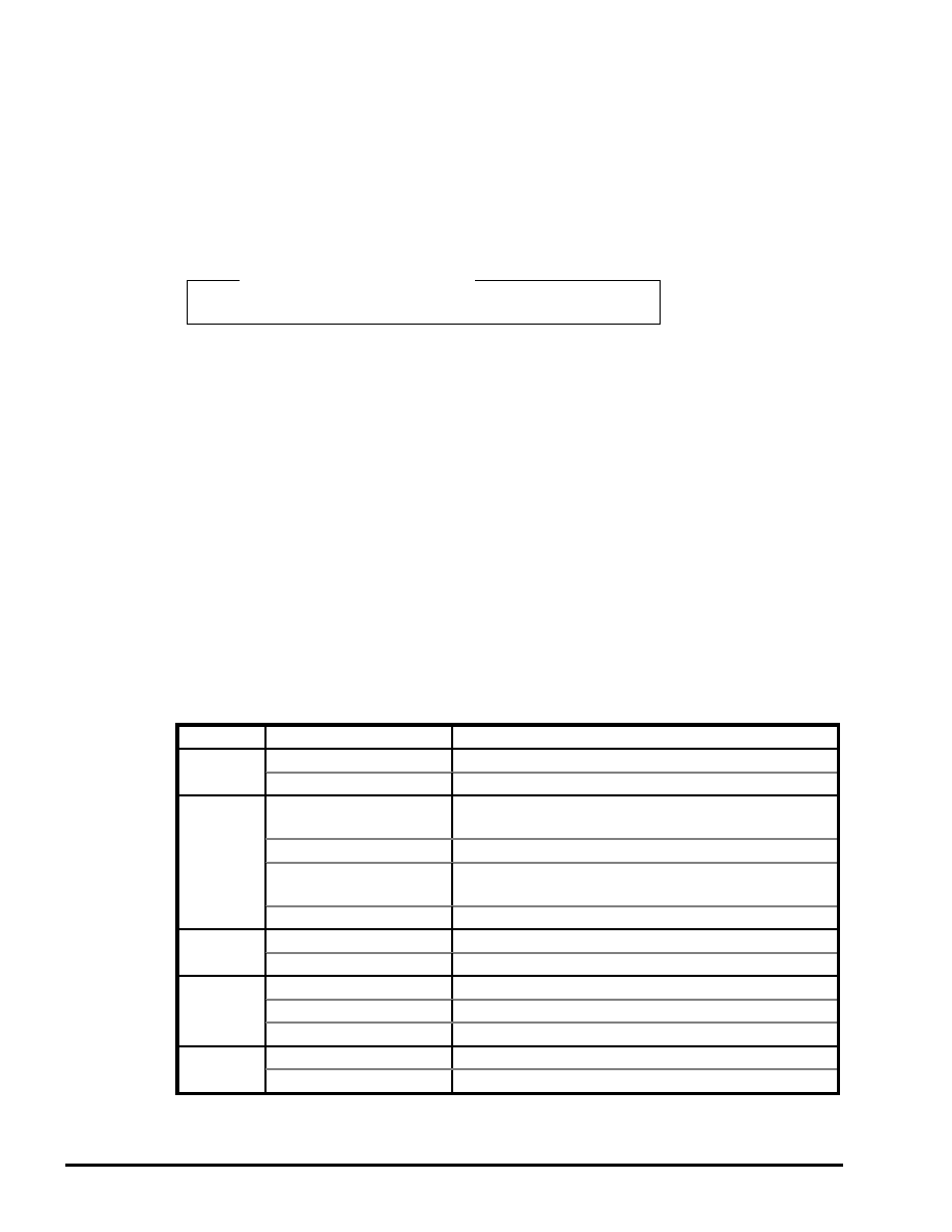
4
2. List of substitution values for the ATTRIBUTE macro
The ATTRIBUTE macro structure and a list of the macro substitution values that can be
used in the SGL for each member in the ATTRIBUTE macro structure are shown below. For
details on the polygon face attribute settings made by the ATTRIBUTE macro and
examples of actual usage, refer to chapter 7, "Polygon Face Attributes," in the
Programmer' s Tutorial.
Fig. 2-1 ATTRIBUTE Macro Structure
_oe
ATTRIBUTE macro structure
_oe
ATTRIBUTE(plane , sort , texture , color , gouraud , mode , dir , option)
Note: The ATTRIBUTE macro is defined in "sl_def.h".
The ATTRIBUTE macro includes the following members.
For the macro substitution values for each member, refer to the list.
plane:
Specifies the front/back attribute.
sort:
Determines the Z sort representative point.
texture: Substitute either a texture number or "No_Texture".
color:
Substitute either a polygon face color specified by the C_RGB macro or
"No_Palet".
gouraud: Specifies the starting address of the area where the gouraud table is stored. If
gouraud processing is not to be used, substitute "No_Gouraud".
mode:
Specifies various modes for the polygon. Multiple specification is possible by
using the "or" operator, "|" to link the substitution values for each group.
dir:
Sets the texture reversal function, etc.
option: Sets other polygon options; multiple specification is possible by using the "or"
operator, "|". If no options are to be used, substitute "No_Option".
Table 2-1. List of ATTRIBUTE Macro Substitution Values (1/3)
Member
Macro
Contents
plane
Singl_Plane
Treats polygon as a single-sided polygon.
Dual_Plane
Treats polygon as a double-sided polygon.
sort
SORT_MIN
Makes the point closest to the camera on the polygon the
reference point.
SORT_CEN
Makes the center point of the polygon the reference point.
SORT_MAX
Makes the point farthest from the camera on the polygon
the reference point.
SORT_BFR
Displays the polygon that was registered last in front.
texutre
Uint16 texno
Texture number of the texture to be used
No_Texture
No texture used
color
C_RGB(r, g, b)
Color specification using the C_RGB macro
Uint16 color
Color palette number or color bank number
No_Palet
Do not use color palette (when texture is in RGB mode)
gouraud
Uint16 GRaddr
Offset value for area where gouraud table is stored (8H)
No_Gouraud
Gouraud processing not used
Note:
The values in the above table are defined in "sl_def.h", provided with the system.
|
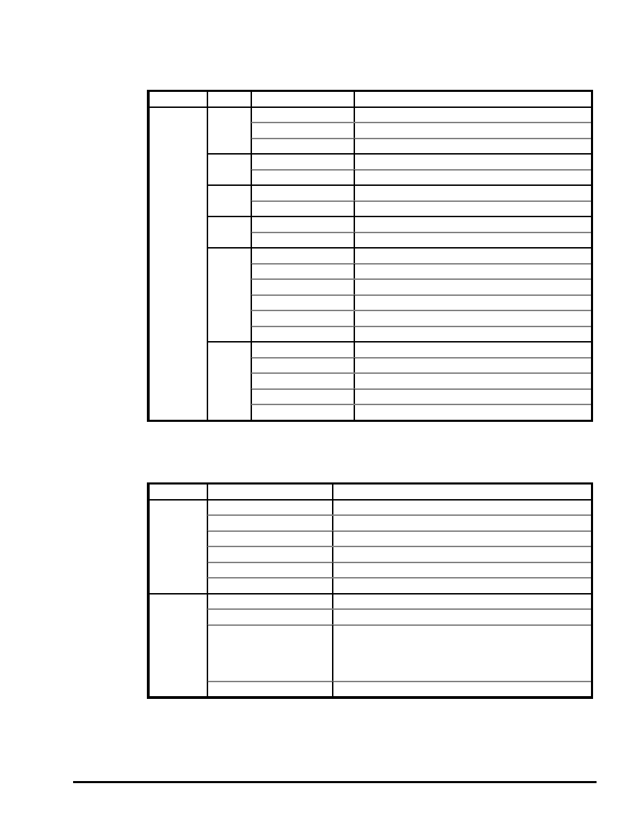
5
Table 2-1. List of ATTRIBUTE Macro Substitution Values (2/3)
Member
Group
Macro
Contents
mode
No_Window
No restrictions concerning window (default)
[1]
Window_In
Display inside window
Window_Out
Display outside window
[2]
MESHoff
Normal display (default)
MESHon
Mesh display
[3]
ECdis
Disable EndCode
ECenb
Enable EndCode (default)
[4]
SPdis
Display transparent pixels (default)
SPenb
Do not display transparent pixels
CL16Bnk
16-color color bank mode (default)
CL16Look
16-color look-up mode
[5]
CL64Bnk
64-color color bank mode
CL128Bnk
128-color color bank mode
CL256Bnk
256-color color bank mode
CL32KRGB
32,768 RGB mode
CL_Replace
Overwrite mode (default)
Cl_Shadow
Shadow mode
[6]
CL_Half
Semi-bright mode
CL_Trans
Semi-transparent mode
CL_Gouraud
Gouraud shading mode
Note: The values in the above table are defined in "sl_def.h", provided with the system.
Table 2-1. List of ATTRIBUTE Macro Substitution Values (3/3)
Member
Macro
Contents
dir
sprNoflip
Display texture normally
sprHflip
Flip texture horizontally
sprVflip
Flip texture vertically
sprHVflip
Flip texture horizontally and vertically
sprPolygon
Display polygon
sprPolyLine
Display polyline
option
UseLight
Make light source calculations
UseClip
Do not display vertices outside of viewing area
UsePalette
Specify with
"
UseLight
"
when performing light source
calcutations for a palette mode polygon. In this case, 8
colors are selected from the specified palette number
according to brightness (+0 is low brightness).
No_Option
No options used
Note: The values in the above table are defined in "sl_def.h", provided with the system.
Note:
Restriction on texture specifications:
If a texture is not used on an object, do not specify "sprHflip" or "sprVflip".
|
SGL Reference
Memory Map
In the Sega Graphics Library, a portion of memory is used by
the system.
In general terms, memory is used as shown in the illustration
below. This chapter provides more detailed information on
how memory is used.
Fig.
Map of Entire Memory Area
VDP1 area
VDP2 area
Work RAM area
*Cache address
25C00000
25E00000
26000000
(06000000)
|
2
1 . General
The SGL system uses 0x40000 bytes in the WORK RAM-H area for sprite and scroll
control. In addition, 264 bytes in VDP1 VRAM is used for gouraud shading when showing
light source effects on textures. A breakdown of this area and the default settings are shown
below.
VRAM breakdown
Default value
MAX_POLYGON (number of polygons that can be used)
: 1800
MAX_VERTICES (number of vertices that can be used)
: 2500
MAX_TRANSFER (number of transfer requests during
blanking)
: 20
MAX_NEST (number of nested matrices)
: 20
Fig. 1-1 Breakdown of VDP1 VRAM and the Default Values
When a model is specified by "slPutPolygon", that model is not processed if the total
number of polygons or vertices (including that model) will exceed the respective maximum.
In addition, each time "slPutSprite()", "slDispSprite", and "slSetSprite()" are executed, the
number of polygons increases by one; if the maximum limit is exceeded, processing of that
data is halted. (However, if the specified Z position is outside of the display area, that sprite
is not counted.)
|
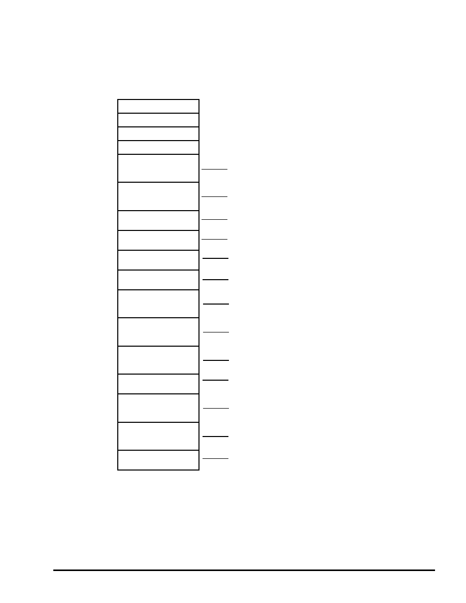
3
2 . WORK RAM-H
BootROMBIOSfunctions
SlaveCPUStackArea
MasterCPUdefaultStack
???
UserProgram&Data
User area
SortList (549C)
Table buffer for DMA transfers of sprite control data
(MAX_POLYGON+5)*3*4BYTE = 0x549C
TransList (F0)
DMA control table for transfer requests during blanking
MAX_TRANSFER*3*4BYTE = 0xF0
Zbuffer (200)
Primary buffer for polygon sort (for window 0)
128*4 = 0x200
Zbuffer2 (200)
Primary buffer 2 polygon sort (for window 1)
128*4 = 0x200
Zbuf_nest (400)
Secondary buffer for polygon sort
256*4 = 0x400
Spritebuf (FDD4)
Sprite control data buffer
(MAX_POSYGON+5)*36 = 0xFDD4
Spritebuf2 (FDD4)
Sprite control data buffer 2
(MAX_POSYGON+5)*36 = 0xFDD4
Pbuffer (9C40)
Vertex position buffer for polygon calculations
MAX_VERTICES*16 = 0x9C40
CLOfstBuf (420)
Data table for colors generated due to light source effects
33*32 = 0x420
CommandBuf (E100)
Command passing buffer from master to slave
MAX_POLYGON*32 = 0xE100
StackArea (216C)
Stack area (0x216C)
SystemWork (400)
System variable area (the GBR register always points here)
0x400byte
Fig.2-1 Work RAM-H Memory Map
Cache_address
06000000
06000800
06001000
06002000
06004000
060C0000
060C549C
060C558C
060C578C
060C598C
060C5D8C
060D5B60
060E5934
060EF574
060EF994
060FDA94
060FFC00
06100000
|

4
System variables
The system variables are shown below; these variables can also be called from a C program.
000
(EventTop)
(EVENT*)
First registered event
004
(EventLast)
(EVENT*)
Last registered event
008
(EventNow)
(EVENT*)
Event being executed
00C
(EventCount)
(Uint16)
Number of events remaining
00E
(WorkCount)
(Uint16)
Number of work areas remaining
010
(MainMode)
(Uint8)
Main sequence mode
011
(SubMode)
(Uint8)
Sub sequence mode
012
(SynchConst)
(Sint8)
Video sync count
013
(SynchCount)
(Sint8)
Video sync count
014
(UserFunction)
(void (*)())
User function to be executed during blanking
018
(TransCount)
(Uint16)
Number of transfer entries during blanking
01A
(TransRequest)
(Uint8)
Transfer request during blanking
01C
(mtptr)
(MATRIX *)
Current matrix pointer
020
(MatrixCount)
(Uint16)
Matrix nest count
022
(IntCount)
(Uint16)
Interrupt count
024
(MsPbufPtr)
(Uint32 *)
Vertex coordinate calculation buffer pointer (master)
028
(SlPbufPtr)
(Uint32 *)
Vertex coordinate calculation buffer pointer (slave)
02C
(SpritePtr)
(Uint16 *)
Sprite data transfer pointer
030
(MsSdataPtr)
(Uint16 *)
Sprite data set pointer (Master)
034
(SlSdataPtr)
(Uint16 *)
Sprite data set pointer (Master)
038
(ZbufPtr)
(void **)
Z buffer pointer
03C
(FormTbl)
(TEXTURE *)
Texture data table
040
(SprbufBias)
(Uint32)
Sprite data buffer switching
044
(ComRdPtr)
(Uint32 *)
Command read pointer
048
(ComWrPtr)
(Uint32 *)
Command set pointer
04C
(MsLight)
(VECTOR)
Light source vector (master)
058
(SlLight)
(VECTOR)
Light source vector (master)
064
(ColorOffset)
(Uint8 *)
Color offset table pointer
068
(MsScreenDist)
(FIXED)
Screen position (master)
06C
(SlScreenDist)
(FIXED)
Screen position (slave)
070
(MsZlimit)
(Sint16)
Display limit Z position (master)
072
(WindowNumber)
(Uint8)
Number of windows used
073
(WinUseFlag)
(Uint8)
Window use flag
074
(TotalPolygons)
(Uint16)
Total number of polygons
076
(TotalVertices)
(Uint16)
Total number of vertices
078
(MsScreenLeft)
(Sint16)
Screen left position (master)
07A
(MsScreenTop)
(Sint16)
Screen top position (master)
07C
(MsScreenRight)
(Sint16)
Screen right position (master)
07E
(MsScreenBottom)
(Sint16)
Screen bottom position (master)
|

5
080
(MsScreenSizeX)
(Uint16)
Horizontal screen size (master)
082
(MsScreenSizeY)
(Uint16)
Vertical screen size (master)
084
(MsScreenHalfX)
(Uint16)
Horizontal screen size/2 (master)
086
(MsScreenHalfY)
(Uint16)
Vertical screen size/2 (master)
088
(SlScreenLeft)
(Sint16)
Screen left position (slave)
08A
(SlScreenTop)
(Sint16)
Screen top position (slave)
08C
(SlScreenRight)
(Sint16)
Screen right position (slave)
08E
(SlScreenBottom)
(Sint16)
Screen bottom position (slave)
090
(SlScreenSizeX)
(Sint16)
Horizontal screen size (slave)
092
(SlScreenSizeY)
(Uint16)
Vertical screen size (slave)
094
(SlScreenHalfX)
(Uint16)
Horizontal screen size/2 (slave)
096
(SlScreenHalfY)
(Uint16)
Vertical screen size/2 (slave)
098
(MsClipXAdder)
(Sint16)
Clipping calculation data (horizontal) (master)
09A
(MsClipYAdder)
(Sint16)
Clipping calculation data (vertical) (master)
09C
(SlClipXAdder)
(Sint16)
Clipping calculation data (horizontal) (slave)
09E
(SlClipYAdder)
(Sint16)
Clipping calculation data (vertical) (slave)
0A0
(SlZlimit)
(Sint16)
Display limit Z position (slave)
0A2
(WinPtr)
(Uint16)
Window data set offset
0A4
(DispPolygons)
(Uint16)
Number of display polygons
0A6
(DMAEndFlag)
(Uint8)
DMA transfer end flag (not used)
0A8
(DMASetFlag)
(Uint8)
DMA table set flag
0AA
(PutCount)
(Uint16)
Number of slPutPolygon(), sl...Sprite() calls
0AC
(MsZdpsftcnt)
(Uint8)
Screen display limit shift count (master)
0AD
(SlZdpsftcnt)
(Uint8)
Screen display limit shift count (Slave)
0B0
(Randwork)
(Uint32)
Random number generator work area
0C0
(VDP2_TVMD)
(Uint16)
TV screen mode
0C2
(VDP2_EXTEN)
(Uint16)
External signal enable
0C4
(VDP2_TVSTAT)
(Uint16)
Screen status
0C6
(VDP2_VRSIZE)
(Uint16)
VRAM size
0C8
(VDP2_HCNT)
(Uint16)
H counter
0CA
(VDP2_VCNT)
(Uint16)
V counter
0CE
(VDP2_RAMCTL)
(Uint16)
RAM control
|

6
0D0
(VDP2_CYCA0L)
(Uint16)
VRAM cycle pattern (bank A0, T0 to 3)
0D2
(VDP2_CYCA0U)
(Uint16)
VRAM cycle pattern (bank A0, T4 to 7)
0D4
(VDP2_CYCA1L)
(Uint16)
VRAM cycle pattern (bank A1, T0 to 3)
0D6
(VDP2_CYCA1U)
(Uint16)
VRAM cycle pattern (bank A1, T4 to 7)
0D8
(VDP2_CYCB0L)
(Uint16)
VRAM cycle pattern (bank B0, T0 to 3)
0DA
(VDP2_CYCB0U)
(Uint16)
VRAM cycle pattern (bank B0, T4 to 7)
0DC
(VDP2_CYCB1L)
(Uint16)
VRAM cycle pattern (bank B1, T0 to 3)
0DE
(VDP2_CYCB1U)
(Uint16)
VRAM cycle pattern (bank B1, T4 to 7)
0E0
(VDP2_BGON)
(Uint16)
Screen display enable
0E2
(VDP2_MZCTL)
(Uint16)
Mosaic control
0E4
(VDP2_SFSEL)
(Uint16)
Special function code select
0E6
(VDP2_SFCODE)
(Uint16)
Special function code
0E8
(VDP2_CHCTLA)
(Uint16)
Character control (NBG0, NBG1)
0EA
(VDP2_CHCTLB)
(Uint16)
Character control (NBG2, NBG3, RBG0)
0EC
(VDP2_BMPNA)
(Uint16)
Bit map palette number (NBG0, 1)
0EE
(VDP2_BMPNB)
(Uint16)
Bit map palette number (RBG0)
0F0
(VDP2_PNCN0)
(Uint16)
Pattern name control (NBG0)
0F2
(VDP2_PNCN1)
(Uint16)
Pattern name control (NBG1)
0F4
(VDP2_PNCN2)
(Uint16)
Pattern name control (NBG2)
0F6
(VDP2_PNCN3)
(Uint16)
Pattern name control (NBG3)
0F8
(VDP2_PNCR)
(Uint16)
Pattern name control (RBG0)
0FA
(VDP2_PLSZ)
(Uint16)
Plane size
0FC
(VDP2_MPOFN)
(Uint16)
Map offset (NBG0 to 3)
0FE
(VDP2_MPOFR)
(Uint16)
Map offset (rotation parameters A, B)
100
(VDP2_MPABN0)
(Uint16)
Map (NBG0 plane A, B)
102
(VDP2_MPCDN0)
(Uint16)
Map (NBG0 plane C, D)
104
(VDP2_MPABN1)
(Uint16)
Map (NBG1 plane A, B)
106
(VDP2_MPCDN1)
(Uint16)
Map (NBG1 plane C, D)
108
(VDP2_MPABN2)
(Uint16)
Map (NBG2 plane A, B)
10A
(VDP2_MPCDN2)
(Uint16)
Map (NBG2 plane C, D)
10C
(VDP2_MPABN3)
(Uint16)
Map (NBG3 plane A, B)
10E
(VDP2_MPCDN3)
(Uint16)
Map (NBG3 plane C, D)
110
(VDP2_MPABRA)
(Uint16)
Map (Rotation parameters A plane A, B)
112
(VDP2_MPCDRA)
(Uint16)
Map (Rotation parameters A plane C, D)
114
(VDP2_MPEFRA)
(Uint16)
Map (Rotation parameters A plane E, F)
116
(VDP2_MPGHRA)
(Uint16)
Map (Rotation parameters A plane G, H)
118
(VDP2_MPIJRA)
(Uint16)
Map (Rotation parameters A plane I, J)
11A
(VDP2_MPKLRA)
(Uint16)
Map (Rotation parameters A plane K, L)
11C
(VDP2_MPMNRA)
(Uint16)
Map (Rotation parameters A plane M, N)
11E
(VDP2_MPOPRA)
(Uint16)
Map (Rotation parameters A plane O, P)
|

7
120
(VDP2_MPABRB)
(Uint16)
Map (Rotation parameters B plane A, B)
122
(VDP2_MPCDRB)
(Uint16)
Map (Rotation parameters B plane C, D)
124
(VDP2_MPEFRB)
(Uint16)
Map (Rotation parameters B plane E, F)
126
(VDP2_MPGHRB)
(Uint16)
Map (Rotation parameters B plane G, H)
128
(VDP2_MPIJRB)
(Uint16)
Map (Rotation parameters B plane I, J)
12A
(VDP2_MPKLRB)
(Uint16)
Map (Rotation parameters B plane K, L)
12C
(VDP2_MPMNRB)
(Uint16)
Map (Rotation parameters B plane M, N)
12E
(VDP2_MPOPRB)
(Uint16)
Map (Rotation parameters B plane O, P)
130
(VDP2_SCXN0)
(FIXED)
Screen scroll value (NBG0, horizontal direction, fixed-point)
130
(VDP2_SCXIN0)
(Sint16)
Screen scroll value (NBG0, horizontal direction, integer portion)
132
(VDP2_SCXDN0)
(Uint16)
Screen scroll value (NBG0, horizontal direction, decimal portion)
134
(VDP2_SCYN0)
(FIXED)
Screen scroll value (NBG0, vertical direction, fixed-point)
134
(VDP2_SCYIN0)
(Uint16)
Screen scroll value (NBG0, vertical direction, integer portion)
136
(VDP2_SCDN0)
(Uint16)
Screen scroll value (NBG0, vertical direction, decimal portion)
138
(VDP2_ZMXN0)
(FIXED)
Coordinate increment step (NBG0, horizontal direction, fixed-point)
138
(VDP2_ZMXIN0)
(Uint16)
Coordinate increment step (NBG0, horizontal direction, integer portion)
13A
(VDP2_ZMXDN0)
(Uint16)
Coordinate increment step (NBG0, horizontal direction, decimal portion)
13C
(VDP2_ZMYN0)
(FIXED)
Coordinate increment step (NBG0, vertical direction, fixed-point)
13C
(VDP2_ZMXIN0)
(Uint16)
Coordinate increment step (NBG0, vertical direction, integer portion)
13E
(VDP2_ZMYDN0)
(Uint16)
Coordinate increment step (NBG0, vertical direction, decimal portion)
140
(VDP2_SCXN1)
(FIXED)
Screen scroll value (NBG1, horizontal direction, fixed-point)
140
(VDP2_SCXIN1)
(Uint16)
Screen scroll value (NBG1, horizontal direction, integer portion)
142
(VDP2_SCXDN1)
(Uint16)
Screen scroll value (NBG1, horizontal direction, decimal portion)
144
(VDP2_SCYN1)
(FIXED)
Screen scroll value (NBG1, vertical direction, fixed-point)
144
(VDP2_SCYIN1)
(Uint16)
Screen scroll value (NBG1, vertical direction, integer portion)
146
(VDP2_SCYDN1)
(Uint16)
Screen scroll value (NBG1, vertical direction, decimal portion)
148
(VDP2_ZMXN1)
(FIXED)
Coordinate increment step (NBG1, horizontal direction, fixed-point)
148
(VDP2_ZMXIN1)
(Uint16)
Coordinate increment step (NBG1, horizontal direction, integer portion)
14A
(VDP2_ZMXDN1)
(Uint16)
Coordinate increment step (NBG1, horizontal direction, decimal portion)
14C
(VDP2_ZMYN1)
(FIXED)
Coordinate increment step (NBG1, vertical direction, fixed-point)
14C
(VDP2_ZMYIN1)
(Uint16)
Coordinate increment step (NBG1, vertical direction, integer portion)
14E
(VDP2_ZMXDN1)
(Uint16)
Coordinate increment step (NBG1, vertical direction, decimal portion)
150
(VDP2_SCXN2)
(Uint16)
Screen scroll value (NBG2, horizontal direction)
152
(VDP2_SCYN2)
(Uint16)
Screen scroll value (NBG2, vertical direction)
154
(VDP2_SCXN3)
(Uint16)
Screen scroll value (NBG3, horizontal direction)
156
(VDP2_SCYN3)
(Uint16)
Screen scroll value (NBG3, vertical direction)
158
(VDP2_ZMCTL)
(Uint16)
Reduction enable
15A
(VDP2_SCRCTL)
(Uint16)
Line and vertical cell scroll control
15C
(VDP2_VCSTA)
(Uint16*)
Vertical cell scroll table address
160
(VDP2_LSTA0)
(Sint16*)
Line scroll table address for NBG0
164
(VDP2_LSTA1)
(Sint16*)
Line scroll table address for NBG1
168
(VDP2_LCTA)
(Uint16*)
Line color screen table address
16C
(VDP2_BKTA)
(Uint16*)
Background screen table address
|

8
170
(VDP2_RPMD)
(Uint16)
Rotation parameter mode
172
(VDP2_RPRCTL)
(Uint16)
Rotation parameter read control
174
(VDP2_KTCTL)
(Uint16)
Coefficient table control
176
(VDP2_KTAOF)
(Uint16)
Coefficient table address offset
178
(VDP2_OVPNRA)
(Uint16)
Screen overflow pattern name
17A
(VDP2_OVPNRB)
(Uint16)
Screen overflow pattern name
17C
(VDP2_RPTA)
(Sint32*)
Rotation parameter table address
180
(VDP2_WPSX0)
(Uint16)
Window position (Hstart)
182
(VDP2_WPSY0)
(Uint16)
Window position (Vstart)
184
(VDP2_WPEX0)
(Uint16)
Window position (Hstop)
186
(VDP2_WPEY0)
(Uint16)
Window position (Vstop)
188
(VDP2_WPSX1)
(Uint16)
Window position (Hstart)
18A
(VDP2_WPSY1)
(Uint16)
Window position (Vstart)
18C
(VDP2_WPEX1)
(Uint16)
Window position (Hstop)
18E
(VDP2_WPEY1)
(Uint16)
Window position (Vstop)
190
(VDP2_WCTLA)
(Uint16)
Window control
192
(VDP2_WCTLB)
(Uint16)
Window control
194
(VDP2_WCTLC)
(Uint16)
Window control
196
(VDP2_WCTLD)
(Uint16)
Window control
198
(VDP2_LWTA0)
(Uint16*)
Line window table address
19C
(VDP2_LWTA1)
(Uint16)
Sprite control
1A0
(VDP2_SPCTL)
(Uint16)
Shadow control
1A2
(VDP2_SDCTL)
(Uint16)
Color RAM address offset (NBG0 to 3)
1A4
(VDP2_CRAOFA)
(Uint16)
Color RAM address offset (RBG0, sprite)
1A6
(VDP2_CRAOFB)
(Uint16)
Line color screen enable
1A8
(VDP2_LNCLEN)
(Uint16)
Special priority mode
1AA
(VDP2_SFPRMD)
(Uint16)
Color calculation control
1AC
(VDP2_CCCTL)
(Uint16)
Special color calculation mode
1AE
(VDP2_SFCCMD)
(Uint16)
Priority number
1B0
(VDP2_PRISA)
(Uint16)
Priority number
1B2
(VDP2_PRISB)
(Uint16)
Priority number
1B4
(VDP2_PRISC)
(Uint16)
Priority number
1B6
(VDP2_PRISD)
(Uint16)
Priority number
1B8
(VDP2_PRINA)
(Uint16)
Priority number
1BA
(VDP2_PRINB)
(Uint16)
Priority number
1BC
(VDP2_PRIR)
(Uint16)
Color calculation ratio (sprite 0, 1)
1C0
(VDP2_CCRSA)
(Uint16)
Color calculation ratio (sprite 2, 3)
1C2
(VDP2_CCRSB)
(Uint16)
Color calculation ratio (sprite 4, 5)
1C4
(CCRSB_CCRSC)
(Uint16)
Color calculation ratio (sprite 6, 7)
1C6
(VDP2_CCRSD)
(Uint16)
Color calculation ratio (NBG0, 1)
1C8
(VDP2_CCRNA)
(Uint16)
Color calculation ratio (NBG2, 3)
1CA
(VDP2_CCRNB)
(Uint16)
Color calculation ratio (RBG0)
1CC
(VDP2_CCRR)
(Uint16)
Color calculation ratio (line color screen, background screen)
|

9
1CE
(VDP2_CCRLB)
(Uint16)
Color offset enable
1D0
(VDP2_CLOFEN)
(Uint16)
Color offset select
1D2
(VDP2_CLOFSL)
(Uint16)
Color offset A (red)
1D4
(VDP2_COAR)
(Uint16)
Color offset A (green)
1D6
(VDP2_COAG)
(Uint16)
** PAGE 9
1D8
(VDP2_COAB)
(Uint16)
Color offset A (blue)
1DA
(VDP2_COBR)
(Uint16)
Color offset B (red)
1DC
(VDP2_COBG)
(Uint16)
Color offset B (green)
1DE
(VDP2_COBB)
(Uint16)
Color offset B (blue)
1E0
(ScrRotPtr)
(ROTSCROLL*) Address of rotation parameters being used
1E4
(nbg0_char_adr)
(void*)
CG address for NBG0
1E8
(nbg1_char_adr)
(void*)
CG address for NBG1
1EC
(nbg2_char_adr)
(void*)
CG address for NBG2
1F0
(nbg3_char_adr)
(void*)
CG address for NBG3
1F4
(ra_char_adr)
(void*)
Pattern name address for rotating scroll (parameters A)
1F8
(rb_char_adr)
(void*)
Pattern name address for rotating scroll (parameters B)
1FC
(nbg0_page_adr)
(void*)
Pattern name address for NBG0
200
(nbg1_page_adr)
(void*)
Pattern name address for NBG1
204
(nbg2_page_adr)
(void*)
Pattern name address for NBG2
208
(nbg3_page_adr)
(void*)
Pattern name address for NBG3
20C
(ra_page_adr)
(void*)
Pattern name address for rotating scroll (parameters A)
210
(rb_page_adr)
(void*)
Pattern name address for rotating scroll (parameters B)
214
(rpara_vram_adr)
(void*)
Rotation parameter set address
218
(k_table_adr)
(FIXED*)
Coefficient table set address
21C
(scr_work)
(Uint8[60])
Work area for slAutoDisp
278
(RotScrParA)
(ROTSCROLL*) Rotation parameters A
2E0
(RotScrParB)
(ROTSCROLL)
Rotation parameters B
348
(Window_data)
(Uint16[18])
Window control data buffer (for two)
36C
(Center_data)
(Uint16[10])
Window center control data buffer (for two)
|

10
3 . VDP1 VRAM Memory Map
Because the first and last parts of the VDP1 VRAM that begins at 0x25C00000 is used by
the system, those areas cannot be used by the user.
SpriteCommand(E1C90)
Sprite control command
(MAX_POLYGON + 6)*32 = 0xE1C0
Free (forUser)
User Area
Gouraud shading table
2*4*33 = 0x108 (264)
Fig. 3-1 VDP1 VRAM Memory Map
Cache_through_address
25C00000
25C0E1C0
25C7FEF8
25C80000
|
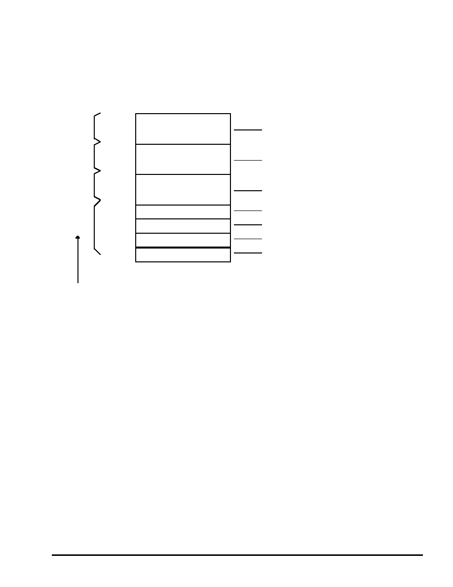
11
4 . VDP2 VRAM Memory Map
The VDP2 VRAM that begins at 0x25E00000 is divided as follows upon system
initialization.
A0
RBG0CG (2048chars)
Character generator data for rotating scroll
A1
RBG0Ktable
Coefficient data and rotation parameters for
rotating scroll
B0
RBG0Map(32pages)
32 pages of pattern name data for rotating
scroll
NBG0,NBG1CG(512chars)
(character generator data for NBG0 and NBG1)
B1
NBG1CG(*896chars)
(character generator data for NBG1)
nbg0map(1page)
(1 page of pattern name data for NBG0)
NBG1Map(4pages)
(4 pages of pattern name data for NBG1)
Normal scroll data (this area is shared by character
generator data and pattern name data)
Fig. 4-1 VDP2 VRAM Memory Map
Settings at system initialization
The character generator is in 256-color mode regardless of the scroll, and the pattern name
is always [1 word/1 cell].
NBG0 is in 10-bit mode with a reverse flag for each cell, while the other screens are in 12-bit
mode in which reverse is specified or not for the entire screen.
The color RAM is in 16-bit, 2048-color mode, and no offset is used.
The background screen is in single-color mode, with the color data (0000) in 25E3FFFE.
Cache_through_address
25E00000
25E20000
25E40000
25E60000
25E68000
25E96000
25E78000
25E80000
|