
SEGA Confidential
General Notice
When using this document, keep the following in mind:
1. This document is confidential. By accepting this document you acknowledge that you are bound
by the terms set forth in the non-disclosure and confidentiality agreement signed separately and /in
the possession of SEGA. If you have not signed such a non-disclosure agreement, please contact
SEGA immediately and return this document to SEGA.
2. This document may include technical inaccuracies or typographical errors. Changes are periodi-
cally made to the information herein; these changes will be incorporated in new versions of the
document. SEGA may make improvements and/or changes in the product(s) and/or the
program(s) described in this document at any time.
3. No one is permitted to reproduce or duplicate, in any form, the whole or part of this document
without SEGA'S written permission. Request for copies of this document and for technical
information about SEGA products must be made to your authorized SEGA Technical Services
representative.
4. No license is granted by implication or otherwise under any patents, copyrights, trademarks, or
other intellectual property rights of SEGA Enterprises, Ltd., SEGA of America, Inc., or any third
party.
5. Software, circuitry, and other examples described herein are meant merely to indicate the character-
istics and performance of SEGA's products. SEGA assumes no responsibility for any intellectual
property claims or other problems that may result from applications based on the examples
describe herein.
6. It is possible that this document may contain reference to, or information about, SEGA products
(development hardware/software) or services that are not provided in countries other than Japan.
Such references/information must not be construed to mean that SEGA intends to provide such
SEGA products or services in countries other than Japan. Any reference of a SEGA licensed prod-
uct/program in this document is not intended to state or simply that you can use only SEGA's
licensed products/programs. Any functionally equivalent hardware/software can be used instead.
7. SEGA will not be held responsible for any damage to the user that may result from accidents or any
other reasons during operation of the user's equipment, or programs according to this document.
(6/27/95- 002)
NOTE: A reader's comment/correction form is provided with this
document. Please address comments to :
SEGA of America, Inc., Developer Technical Support (att. Evelyn Merritt)
150 Shoreline Drive, Redwood City, CA 94065
SEGA may use or distribute whatever information you supply in any way
it believes appropriate without incurring any obligation to you.
|

SEGA Confidential
TM
VDP 1 Library...................................... 1
VDP 2 Library.................................... 45
Number Calculation Library ........... 87
DSP I/F Library .............................. 107
Program Library
User's Guide 2
Graphics Library
Doc. # ST-157-R1-092994
© 1994-95 SEGA. All Rights Reserved.
|

SEGA Confidential
READER CORRECTION/COMMENT SHEET
Chpt.
pg. #
Correction
Corrections:
General Information:
Your Name
Phone
Document number
Date
Document name
Questions/comments:
Keep us updated!
If you should come across any incorrect or outdated information while reading through the attached
document, or come up with any questions or comments, please let us know so that we can make the
required changes in subsequent revisions. Simply fill out all information below and return this form to
the Developer Technical Support Manager at the address below. Please make more copies of this form if
more space is needed. Thank you.
Fax:
(415) 802-1440
Attn: Sr. Coordinator,
Technical Publications Group
Mail:
SEGA OF AMERICA
Attn: Sr. Coordinator,
Technical Publications Group
130 Shoreline Dr.
Redwood City, CA 94065
Where to send your corrections:
ST-157-R1-092994
Program Library User's Guide 2 Graphics Library
|

SEGA Confidential
i
(This page is blank in the original Japanese document.)
|

SEGA Confidential
ii
Contents
VDP1 Library...................................................................................................................... 1
1.0 VDP1 Basic Processing Guide ........................................................................ 1
1.1 Objective...................................................................................................... 1
1.2 Explanation ................................................................................................. 1
1.3 Example of a Program Description ......................................................... 2
2.0 VDP1 Expanded Processing Guide ............................................................... 4
2.1 Objective...................................................................................................... 4
2.2 How to Control the VRAM Area ............................................................. 4
2.3 Drawing Order to the Sprite Command Frame Buffer ........................ 6
2.4 Example of a Program Description ......................................................... 7
3.0 VDP1 3D Guide ................................................................................................ 9
3.1 Objective...................................................................................................... 9
3.2 3D Coordinate System and Display Model ........................................... 9
3.3 Example of a Program Description ......................................................... 10
3.4 Polygon Objects that Connect Between Objects ................................. 13
4.0 VDP1 Basic Processing Reference.................................................................. 15
4.1 Data Specifications .................................................................................... 15
4.2 List of Functions ......................................................................................... 15
4.3 Function Specifications ............................................................................. 16
5.0 VDP1 Expanded Processing Reference......................................................... 19
5.1 Data Specifications .................................................................................... 19
5.2 List of Functions ......................................................................................... 21
5.3 Function Specifications ............................................................................. 22
6.0 VDP1 3D Reference ......................................................................................... 32
6.1 Data Specifications .................................................................................... 32
6.2 List of Functions ......................................................................................... 37
6.3 Function Specifications ............................................................................. 37
VDP2 Library...................................................................................................................... 45
1.0 Guide ................................................................................................................. 45
1.1 Objective...................................................................................................... 45
1.2 Explanation ................................................................................................. 45
1.3 Basic Library Usage ................................................................................... 48
2.0 Reference .......................................................................................................... 55
2.1 Data Specifications .................................................................................... 55
2.2 List of Functions ......................................................................................... 63
2.3 Function Specifications ............................................................................. 65
|

SEGA Confidential
iii
Mathmatical Calculation Library .................................................................................... 87
1.0 Guide ................................................................................................................. 87
1.1 Objective...................................................................................................... 87
2.0 Reference .......................................................................................................... 89
2.1 Data Specifications .................................................................................... 89
2.2 List of Functions ......................................................................................... 91
2.3 Function Specifications ............................................................................. 93
DSP I/F Library ................................................................................................................. 107
1.0 Guide ................................................................................................................. 107
1.1 Objective...................................................................................................... 107
1.2 Overview..................................................................................................... 107
1.3 Function Overview .................................................................................... 107
1.4 Calling Sequence ........................................................................................ 108
2.0 Reference .......................................................................................................... 109
2.1 List of Functions ......................................................................................... 109
2.2 Function Specifications ............................................................................. 109
|

SEGA Confidential
User's Guide 2 Graphics Library
1
VDP1 Library
1.0
VDP1 Basic Processing Guide
1.1
Objective
· Hides hardware-related processing such as VDP1 initialization, register operation,
etc., to reduce the load on the application author.
· Because of differences in processing methods used to speed up applications, the
basic processing library does not write commands to VRAM. The application has
the VRAM addresses, so these can be controlled and written on the application
side.
(Writing to VRAM and VRAM control is supported by the expanded processing
library.)
1.2
Explanation
Initial Processing
· Sets the frame buffer erase area, erase data for each frame change, and the TV
mode.
V-BLANK Interrupt Processing Function
· SPR_WaitDrawEnd () is used in the V_BLANKVDP interrupt routine to check for
VDP1 draw end.
|

SEGA Confidential
2
1.3
Example of a Program Description
#include <machine.h>
#include "sega_spr.h"
#include "sega_scl.h"
#include "sega_int.h"
extern void vbStart (void);
/* V-BLANK IN Interrupt Routine
*/
extern void vbEnd (void);
/* V-BLANK OUT Interrupt Routine
*/
main()
{
Uint8
*vram;
/* VRAM Address Storage Area
*/
set_imask(0);
/* Enable Interrupt
*/
SCL_Vdp2Init();
/* Initialize scroll and priority
*/
SCL_SetPriority(SCL_SP0|SCL_SP1|SCL_SP2|SCL_SP3|SCL_SP4|
SCL_SP5|SCL_SP6|SCL_SP7,7);
SCL_SetSpriteMode(SCL_TYPE1,SCL_MIX,SCL_SP_WINDOW);
SPR_Initial(&vram);
/*Initialize Sprite
*/
INT_ChgMsk(INT_MSK_NULL, INT_MSK_VBL_IN | INT_MSK_VBL_OUT);
/* Disable V-BLANK Interrupt
*/
INT_SetFunc(INT_SCU_VBLK_IN, &vbStart);
/* Register V-BLANK IN Interrupt Routine*/
INT_SetFunc(INT_SCU_VBLK_OUT, &vbEnd);
/* Register V-BLANK OUT Interrupt Routine*/
INT_ChgMsk(INT_MSK_VBL_IN | INT_MSK_VBL_OUT, INT_MSK_NULL);
/* Enable V-BLANK Interrupt
*/
SCL_SetFrameInterval(2);
/* Set the frame change interval to */
/* 2/60 seconds
*/
for(;;) |
memcpy(vram,command,sizeof(command));
/* Set the Sprite Command in VRAM
*/
--------
/* Set Scroll Data
*/
SCL_DisplayFrame();
/* Wait for V-BLANK Interrupt
*/
/* Display Sprite and Move Scroll
*/
}
}
|

SEGA Confidential
User's Guide 2 Graphics Library
3
- V-Blank Processing Routine (Separate source file from the main shown on previous
page.) -
#include <machine.h>
#include "sega_spr.h"
#include "sega_scl.h"
#pragma interrupt(VbStart)
#pragma interrupt(VbEnd)
void VbStart(void)
{
SCL_VblankStart(); /* V-Blank Start VDP Interrupt Processing */
--------
/* Other V-Blank Start Processing
*/
}
void VbEnd(void)
{
SCL_VblankEnd();
/* V-Blank End VDP Interrupt Processing */
--------
/* Other V-Blank End Processing
*/
}
|

SEGA Confidential
4
2.0 VDP1 Expanded Processing Guide
2.1
Objective
· Supports functions that were not included in the basic processing library such as
VRAM management and writing sprite commands to VRAM.
· Executes a primitive sprite display command that corresponds to the sprite
command.
2.2
How to Manage the VRAM
Area
The VRAM area (512Kbyte) is assigned as shown below.
00000H
80000H
VRAM Area Reference Switch Command
System Command Area
User Command Area
Gouraud Shading Table Area
Color Lookup Table
Block Pool Area
(Character, Subroutine Command)
Explanation of Each
Area
· VRAM Area Reference Switch Command
Sprite jump command that is used to match the VRAM area 0, 1 for frame change.
· System Command Area
This area is used to open the access routine used to erase the frame buffer with
polygon draw when the frame change interval is insufficient. Areas 0 and 1 are
the same size.
· User Command Area
Area where sprite commands organized from the top down through the various
command set routines called from the SPR_2OpenCommand() to the
SPR_2CloseCommand() routine. Areas 0 and 1 are the same size.
|

SEGA Confidential
User's Guide 2 Graphics Library
5
· Gouraud Shading Table Area
Area that stores the Gouraud shading table with 8 bytes for each entry and controls
numbers starting at 0. Areas 0 and 1 are the same size.
· Color Lookup Table Area
Area that stores the Color Lookup table with 8 bytes for each entry and controls
numbers starting at 0. Areas 0 and 1 are the same size. Areas 0 and 1 are referenced
commonly.
· Block Pool Area
Area that is referenced by both command areas 0 and 1 and contains character data
and sub-routine commands, etc. (Subroutine commands are currently not
supported.) Character data is controlled starting at number 0. The assigning of
character data, etc., to this area is dynamically acquired and released in 32 byte
blocks.
The Assigned Size of Each
Area
The size of each area is assigned as shown below; one block is 32 bytes.
COMMAND_MAX
: Maximum number of commands
GOUR_TBL_MAX
: Maximum number of Gouraud shading tables
LOOKUP_TBL_MAX
: Maximum number of lookup tables
These values are defined later in the VDP1 expanded processing work area
definition macro.
Block Assign Algorithm Inside the Block Pool
Area
· When Acquiring
Searches for a contiguous block that will hold the block that is being requested and
assigns it the minimum area.
· When Releasing
Releases the designated block area. If there is an empty block next to the block being
released, both blocks are combined to form a large empty block.
Area Name
Blocks
VRAM Area Reference Switch Command
1
System Command Area
4x2
User Command Area
COMMAND_MAX x2
Gouraud Shading Table Area
(GOUR_TBL_MAX+3)/4x2
Color Lookup Table Area
LOOKUP_TBL_MAX
Block Pool Area
All remaining blocks
|

SEGA Confidential
6
2.3
Drawing Order to the Sprite Command Frame Buffer
The drawing order can be set for each command by setting the draw priority value
when the sprite command set routines below are called up.
SPR_2LocalCoord() SPR_2SysClip() SPR_2UserClip() SPR_2line()
SPR_2polyLine() SPR_2Polygon() SPR_2NormSpr() SPR_2ScaleSpr()
SPR_2DistSpr() SPR_2Cmd()
The draw priority number indicates the draw block number. Block number 0 is
drawn first. Also, commands within the blocks are drawn in the order they were
recorded.
Drawing Order
0
1
2
n
Block 0
Block 1
Block 2
Block n
Priority Number
Command Registered Order
The drawing order is set by calling up the SPR_2CloseCommand() or
SPR_2FlushDrawPrty() routines. The control word jump and link settings in the
command can be changed here.
The number of blocks in the draw order number control block are set in advance. It
can be set in the 2D work area definition or the SPR_2OpenCommand () if the draw
area is not to be attached.
|

SEGA Confidential
User's Guide 2 Graphics Library
7
2.4
Example of a Program Description
An actual example program in C language is shown below.
#include machine.h>
#define _SPR2_
/* Use Sprite Display Extended Library
*/
#include "sega_spr.h"
#include "sega_scl.h"
#include "sega_int.h
#define COMMAND_MAX
512
/* Maximum commands
*/
#define GOUR_TBL_MAX
512
/* Maximum Gouraud tables
*/
#define LOOKUP_TBL_MAX
512
/* Maximum Lookup tables
*/
#define CHAR_MAX
100
/* Maximum Characters
*/
#define DRAW_PRTY_MAX 256
/* Maximum Draw Priority Blocks
*/
SPR_2DefineWork(work2d, COMMAND_MAX, GOUR_TBL_MAX,
LOOKUP_TBL_MAX, CHAR_MAX)
/* Define 2D Work Area
*/
extern void vbStart(void);
/* V-BLANK IN Interrupt Routine
*/
extern void vbEnd(void);
/* V-BLANK OUT Interrupt Routine
*/
main()
{
set_imask(0);
/* Enable Interrupt
*/
SCL_Vdp2Init();
/* Initialize Scroll and Priority
*/
SCL_SetPriority(SCL_SP0|SCL_SP1|SCL_SP2|SCL_SP3|SCL_SP4|
SCL_SP5|SCL_SP6|SCL_SP7,7);
SCL_SetSpriteMode(SCL_TYPE1,SCL_MIX,SCL_SP_WINDOW);
SPR_2Initial(&work2d);
/*Initialize 2D Sprite Display
*/
INT_ChgMsk(INT_MSK_NULL, INT_MSK_VBL_IN | INT_MSK_VBL_OUT);
/* Disable V-BLANK Interrupt
*/
INT_SetFunc(INT_SCU_VBLK_IN, &vbStart);
/* Register V-BLANK IN Interrupt Routine*/
INT_SetFunc(INT_SCU_VBLK_OUT, &vbEnd);
/* Register V-BLANK OUT Interrupt Routine*/
INT_ChgMsk(INT_MSK_VBL_IN | INT_MSK_VBL_OUT, INT_MSK_NULL);
/* Enable V-BLANK Interrupt
*/
for(;;) {
SPR_2SetChar(...);
/* Set Character Data to VRAM
*/
}
SPR_2FrameChgIntr(0xffff); /* Set the Frame Change Interval */
/* to Undefined
*/
for(;;) {
------------
/* Set Scroll Data
*/
SPR_2OpenCommand(SPR_2DRAW_PRTY_OFF);
/* Open Command Write
*/
SPR_2SysClip(0,&xy);
/* System Clip Area Command
*/
SPR_2LocalCoord(0,&xy); /* Local Coordinates Command
*/
|

SEGA Confidential
8
SPR_2Polygon(...);
/* Each Type of Sprite Command
*/
SPR_2NormSpr(...);
/*
.
.
.
SPR_2CloseCommand() ;
/* Close Command Write
*/
SCL_DisplayFrame() ;
/* Hold Interrupt V_BLANK
*/
/* Display Sprite and Move Scroll
*/
}
}
- V Blank Process Routine (The main above is a separate source file) -
#include machine.h>
#include "sega_spr.h"
#include "sega_scl.h"
#pragma interrupt (VbStart)
#pragma interrupt (VbEnd)
void VbStart(void)
{
SCL_VblankStart();
/* VBlank start VDP Intrrpt. Process*/
--------
/* Other VBlank Start Processes
*/
}
void VbEnd(void)
{
SCL_VblankEnd();
/* VBlank End VDP Interrupt Process */
--------
}
|

SEGA Confidential
User's Guide 2 Graphics Library
9
3.0
VDP1 3D Guide
3.1
Objective
The purpose here is to use the VDP1 expansion processing library to display 3D
sprites.
· Handles layers of connected models that consist of groupings of polygons.
· There is no need to understand the matrix calculations that accompany the
movement of models or the objects within a model.
· The user application is made aware of the coordinate value of the point after
world coordinates have been converted through the user call back routine.
· Texture mapping and sprite coloring during display can also be applied to polygons.
· Can be matched with 2D sprites when displayed.
3.2
3D Coordinate System and Display Model
Coordinate System
Light Source
World Coordinates
View Point
View Point
Coordinate System
Model
screen
Body Coordinate System
Object
y
y
y
x
x
z
z
-z
1
0
0
0
0
Distance from the screen to the view point is fixed at 1.0.
|

SEGA Confidential
10
[Display Model]
The display model is a grouping of polygons connected in a layered cluster as an object.
Clusters have a mother/child-type relationship: the position of the object that is the child
cluster is placed in the mother cluster body coordinate system. For this reason, when the
mother cluster is moved, all of the child clusters move along with it.
Object 1
Cluster 00
Object 0
Cluster 21
Cluster 20
Cluster 12
Cluster 11
Cluster 10
Root Cluster
3.3
Example of a Program Description
An actual example program in C language is shown below.
#include <machine.h>
#define _SPR3_
/* Use Sprite 3D Display Library
*/
#define SPR_3USE_DOUBLE_BUF
/* Designates double buffer
*/
#include "sega_spr.h"
#include "sega_scl.h"
#include "sega_int.h
SprCluster mode10;
SprCluster mode11;
#define COMMAND_MAX 1000
/* Maximum commands
*/
#define GOUR_TBL_MAX 1000
/* Maximum Gouraud tables
*/
#define LOOKUP_TBL_MAX 1000
/* Maximum Lookup tables
*/
#define CHAR_MAX
100
/* Maximum Characters
*/
#define DRAW_PRTY_MAX 256
/* Maximum Draw Priority Blocks
*/
SPR_2DefineWork(work2d, COMMAND_MAX, GOUR_TBL_MAX,
LOOKUP_TBL_MAX, CHAR_MAX, DRAW_PRTY_MAX)
/* Define 2D Work Area
*/
#define OBJ_SURF_MAX 16
/* Maximum Surfaces in an Object
*/
#define OBJ_VERT_MAX 16
/* Max. Vertex Points in an Object */
SPR_3DefineWork(work3D, OBJ_SURF_MAX, OBJ_VERT_MAX)
/* Defines the 3D Work Area
*/
|

SEGA Confidential
User's Guide 2 Graphics Library
11
extern void vbStart(void);
/* V-BLANK IN Interrupt Routine
*/
extern void vbEnd(void);
/* V-BLANK OUT Interrupt Routine
*/
main()
{
set_imask(0);
/* Enable Interrupt
*/
SCL_Vdp2Init();
/* Initialize Scroll and Priority
*/
SCL_SetPriority(SCL_SP0|SCL_SP1|SCL_SP2|SCL_SP3|SCL_SP4|
SCL_SP5|SCL_SP6|SCL_SP7,7);
SCL_SetSpriteMode(SCL_TYPE1,SCL_MIX,SCL_SP_WINDOW);
SPR_2Initial(&work2d);
/*Initialize 2D Sprite Display
*/
SPR_3Initial(&work3D);
/*Initialize 3D Sprite Display
*/
INT_ChgMsk(INT_MSK_NULL, INT_MSK_VBL_IN | INT_MSK_VBL_OUT);
/* Disable V-BLANK Interrupt
*/
INT_SetFunc(INT_SCU_VBLK_IN, &vbStart);
/* Register V-BLANK IN Interrupt Routine*/
INT_SetFunc(INT_SCU_VBLK_OUT, &vbEnd);
/* Register V-BLANK OUT Interrupt Routine*/
INT_ChgMsk(INT_MSK_VBL_IN | INT_MSK_VBL_OUT, INT_MSK_NULL);
/* Enable V-BLANK Interrupt
*/
SPR_2FrameChgIntr(0xffff); /* Set the Frame Change Interval
*/
/* to Undefined
*/
SPR_3SetTexture(texture); /* Set the 3D Texture Data
*/
for(;;) {
------------
/* Set Scroll Data
*/
SPR_3SetLight(...);
/* Set the 3D light Source
*/
SPR_3SetView(...);
/* Set the 3D view Point
*/
SPR_2OpenCommand(SPR_2DRAW_PRTY_ON);
/* Open Sprite Command Write
*/
SPR_2SysClip(SPR_2MOST_FAR,&xy);
/* System Clip Area Command
*/
SPR_2LocalCoord(SPR_2MOST_FAR+1,&xy);
/* Local Coordinates Command
*/
SPR_3moveCluster(mode10,...);/* Move Root Cluster of 3D model 0*/
SPR_3DrawMode1(mode10,...); /* Register 3D Model 0
*/
SPR_3moveCluster(mode11,...);/* Move Root Cluster of 3D model 1*/
SPR_3DrawMode1(mode11,...); /* Register 3D Model 1
*/
.
.
.
SPR_3Flush();
/* Set the 3D Sprite Command
*/
SPR_2CloseCommand() ;
/* Close sprite command Write
*/
SCL_DisplayFrame() ;
/* Hold Interrupt V_BLANK
*/
/* Display Sprite and Move Scroll
*/
}
}
|

SEGA Confidential
12
· V Blank Process Routine (The main above is a separate source file) -
#include <machine.h>
#include "sega_spr.h"
#include "sega_scl.h
#pragma interrupt (VbStart)
#pragma interrupt (VbEnd)
void VbStart(void)
{
SCL_VblankStart();
/* V Blank start VDP Interrupt Process
*/
--------
/* Other VBlank Start Processes
*/
}
void VbEnd(void)
{
SCL_VblankEnd();
/* VBlank End VDP Interrupt Process
*/
--------
/* Other VBlank End Processes
*/
}
Polygon Z sort in the view coordinate system of the sprite 3D display library uses the
sprite priority draw function of the VDP1 expansion library (2D library). To execute
Z sort, priority draw in the SPR_2OpenCommand() routine must be set to on
(SPR_2DRWA_PRTY_ON).
|

SEGA Confidential
User's Guide 2 Graphics Library
13
3.4
Polygon Objects That Connect Between Objects
When Object2 needs to be changed to accomodate the movement of Object1, as
shown in the figure below, define the polygon between Object0 and Object1 (Ob-
ject2) as an inbetween-object polygon and the shape changes are automatically
drawn.
1
2
6
5
4
1
1
0
2
6
5
4
0
3
7
Object1
5
4
0
Object1
Object2
Object0
Object2
Object0
Object Movement
The different tables that contain the cluster, object and inbetween-object polygon
information are connected as shown below.
Cluster0
Cluster1
InbetInf0
Object0
InbetInf1
Object1
Object2
InbetInf: Inbetween object polygon information
child
|

SEGA Confidential
14
· Processing the Inbetween-object Polygon Object
1) Objects are drawn in order from the parent cluster to the child cluster; if there is
more than one object in a cluster, they are drawn in the order they were connected.
In the previous example, objects would be drawn in order of Object0, Object1,
Object2.
2) If there is inbetween-object polygon information connected to the cluster, the
inbetween-object polygon object vector data table is set using the corresponding
vector data converted from the focal point coordinate system in the set table.
If there is Gouraud shading, the calculated vector brightness is set into the
inbetween-object polygon normal vector line data table. In the previous example,
InbetInf0 sets the focal coordinate system vector data (0, 1, 2, 3) to Object2 vector
data (4, 5, 6, 7); InbetInf1 sets the focal coordinate system vector data (4, 5, 6, 7) to
Object2 vector data (0, 1, 2, 3).
3) If the draw object is an inbetween-object polygon, the normal vector for each
surface is found after conversion to the focal coordinate system, and the object is
drawn according to the draw mode. In the previous example, Object2 is the
inbetween-object polygon object.
4) Conditions for setting the inbetween-object polygon.
· If set as one of a cluster, connect it last in the object chain.
· The normal vector calculation correction value in the object table is set as a
negative value.
|
SEGA Confidential
User's Guide 2 Graphics Library
15
4.0 VDP1 Basic Processing Reference
4.1
Data Specifications
typedef struct SprSpStatus {
Uint16 frameChgMode;
/* Frame Change Mode *1
*/
Uint16 frameEraseMode;
/* Frame Erase Mode *2
*/
Uint16 vbInterval;
/* V-BLANK Intervals
*/
Uint16 eraseData;
/* Frame Buffer Erase Data
*/
Uint16 eraseLeftX;
/* Frame Buffer Erase Left Side
*/
Uint16 eraseTopY;
/* Frame Buffer Erase Top
*/
Uint16 eraseRightX;
/* Frame Buffer Erase Right Side
*/
Uint16 eraseBotY;
/* Frame Buffer Erase Bottom
*/
} SprSpStatus;
*1 Frame change Mode
#define AUTO_FRAME_CHG
0 /* Auto Change
*/
#define MANUAL_FRAME_CHG
1 /* Manual Change at Fixed Interval
*/
#define NO_INTERVAL_FRAME_CHG
2 /* Manual Change at Undefined Interval */
#define NO_INTER_VBE_FRAME_CHG
3 /* Undefined by Vblank erase
*/
/* Interval Manual Change
*/
*2 Frame Erase Mode
#define OFF
0 /* Frame Erase OFF
*/
#define ON
1 /* Frame Erase ON
*/
4.2
List of Functions
Function
Function Name
Number
Initialize the VDP1 basic process library
SPR_Initial
1
Set TV Mode
SPR_SetTvMode
2
Get the Current Sprite Control Information
SPR_GetStatus
3
Set the Frame Buffer Erase Area, Erase data
SPR_SetEraseData
4
Check the Frame Buffer Draw End
SPR_WaitDrawEnd
5
Set the Sprite Draw Source Coordinate Select Mode
SPR_SetEosMode
6
System Register Write Macro
SPR_WRITE_REG
7
System Register Read Macro
SPR_READ_REG
8
Title
Data
Data Name
No
Data Specification
Status Return Area Pointer
SPR_SpStatus
|

SEGA Confidential
16
4.3
Function Specifications
Title
Function
Function Name
No
Function Specification
Initialize the VDP1 basic process library
SPR_Initial
1
Format
void SPR_Initial(Uint8 **vram)
Input
vram
:VRAM address return area pointer
Output
None
Function Value
None
Function
Sets the following values as default
· Erase Data = 0x8000 (Black)
· Erase Area = (0, 0) - (319,223)
· TV mode is normal, resolution is 320 X 224
Title
Function
Function Name
No
Function Specification
TV Mode Set
SPR_SetTvMode
2
Format
void
Spr_SetTvMode(Uint16 mode, Uint16 screenSize,
Uint16 doubleInterlace)
Input
mode
: The following TV mode definition values can be set.
SPR_TV_NORMAL
= Normal Mode
SPR_TV_HIREZ0
= Hi Resolution Mode
SPR_TV_R0T16
= Rotate 16 Mode
SPR_TV_R0T8
= Rotate 8 Mode
SPR_TV_HDTV
= HDTV Mode
screenSize : Sets the screen size that corresponds to the TV
mode from the definition values shown below.
See the VDP1 manual for detailed configurations.
SPR_TV_320X224
= 320 x 224
SPR_TV_320X240
= 320 x 240
SPR_TV_352X224
= 352 x 224
SPR_TV_352X240
= 352 x 240
SPR_TV_640X224
= 640 x 224
SPR_TV_640X240
= 640 x 240
SPR_TV_704X224
= 704 x 224
SPR_TV_704X240
= 704 x 240
doubleInterlace : Sets the double interlace mode.
ON = Use the double interlace mode.
OFF = Do not use the double interlace mode.
Output
None
Function Value
None
Function
Sets the TV Mode.
|

SEGA Confidential
User's Guide 2 Graphics Library
17
Title
Function
Function Name
No
Function Specification
Get the Current Sprite Control Information
SPR_GetStatus
3
Format
void SPR_GetStatus(SprSpStatus *spStatus)
Input
None
Output
SprSpStatus: Status return area pointer
Function Value
None
Function
Gets the sprite control information.
Title
Function
Function Name
No
Function Specification
Set the Frame Buffer Erase Area, Erase data SPR_SetEraseData
4
Format
void SPR_SetEraseData(Uint16 eraseData, Uint16 leftX,
Uint16 topY, Uint16 rightX, Uint16 botY)
Input
eraseData: RGB erase data
leftX
: Left erase X coordinates
topY
: Top erase Y coordinates
rightX
: Right erase X coordinates
botY
: Bottom erase Y coordinates
Output
None
Function Value
None
Function
Used to set what color and what area is erased in the erase
process.
Title
Function
Function Name
No
Function Specification
Check the Frame Buffer Draw End
SPR_WaitDrawEnd
5
Format
void SPR_WaitDrawEnd(void)
Input
None
Output
None
Function Value
None
Function
Waits for the VDP1 to finish drawing to the frame buffer. This
routine is called from the V-BLANK VDP interrupt process
routine.
|

SEGA Confidential
18
Title
Function
Function Name
No
Function Specification
Set the Sprite Draw Source
Coordinate Select Mode
SPR_SetEosMode
6
Format
void SPR_SetEosMode(Sint32 eosFlag)
Input
eosFlag :
0= Sampling of even coordinates (default)
1= Sampling of odd coordinates
Output
None
Function Value
None
Function
Sets the source picture texture sampling coordinate mode with
the sprite command draw mode when high speed draw is set.
Title
Function
Function Name
No
Function Specification
System Register Write Macro
SPR_WRITE_REG
7
Format
SPR_WRITE_REG(Uint16 reg, Uint16 val)
Input
reg :
Sets the system register type from the definitions
listed below.
SPR_W_TVMR = Select TV Mode
SPR_W_FBCR = Frame Buffer Change Mode
SPR_W_PTMR = Plot Trigger
SPR_W_EWDR = Erase Write Data
SPR_W_EWLR = Erase Write Upper Left Coordinate
SPR_W_EWRR = Erase Write Lower Right Coordinate
SPR_W_EWDR = End Draw
Value:
Write value
Output
None
Function Value
None
Function
Writes to the VDP1 dedicated write system register.
Title
Function
Function Name
No
Function Specification
System Register Read Macro
SPR_READ_REG
8
Format
Uint16 val = SPR_READ_REG(Uint16 reg)
Input
reg :
Sets the system register type from the definitions
listed below.
SPR_R_EDSR = Transfer End State
SPR_R_LOPR = Process Interrupt Table Address
SPR_R_COPR = Current Process Table Address
SPR_R_MODR = Mode Status
Output
None
Function Value
val :
Read Value
Function
Reads the register value from the VDP1 dedicated read system
register.
|

SEGA Confidential
User's Guide 2 Graphics Library
19
5.0
VDP1 Expanded Processing Reference
5.1
Data Specifications
Title
Data
Data Name
No
Data Specification
Coordinate Indicator Data Type
XyInt
Defined in sega_def.h
typedef struct XyInt {
Sint16 x;
Sint16 y;
} XyInt;
Title
Data
Data Name
No
Data Specification
Gouraud Shading Table
SprGourTbl
typedef struct SprGourTbl {
Uint16 entry[4];
} SprGourTbl;
Title
Data
Data Name
No
Data Specification
Lookup Table Data Type
SprLookupTbl
typedef struct SprLookupTbl {
Uint16 entry[16];
} SprLookupTbl;
Title
Data
Data Name
No
Data Specification
VRAM for Sprite Command Relative
Address Data Type
SprVaddr
typedef Uint16 SprVaddr;
|

SEGA Confidential
20
Title
Data
Data Name
No
Data Specification
Sprite Command Data Types
SprSp Cmd
typedef struct SprSpCmd
{/* Sprite Command Table
*/
Uint16 control;
/* control word
*/
Uint16 link;
/* command link
*/
Uint16 drowMode;
/* drow mode
*/
Uint16 color;
/* color info.
*/
Uint16 charAddr;
/* character address
*/
Uint16 charSize;
/* character size
*/
Sint16 ax;
/* point A x
*/
Sint16 ay;
/* point A y
*/
Sint16 bx;
/* point B x
*/
Sint16 by;
/* point B y
*/
Sint16 cx;
/* point C x
*/
Sint16 cy;
/* point C y
*/
Sint16 dx;
/* point D x
*/
Sint16 dy;
/* point D y
*/
Uint16 grshAddr;
/* goouraud shading table address*/
Uint16 dummy;
/* dummy area
*/
} SprSpCmd;
|

SEGA Confidential
User's Guide 2 Graphics Library
21
5.2
List of Functions
Function
Function Name
Number
VDP1 Expansion Processing Work Area Definition Macro
SPR_2DefineWork
1
Initializing Process for the VDP1 Expansion Processing
Library
SPR_2Initlial
2
Set the TV Mode
SPR_2SetTvMode
3
Set Frame Change V-Blank Interval Count
SPR_2FrameChgIntr
4
Set Frame Buffer Erase Data
SPR_2FrameEraseData
5
Set the Gouraud Shading Table
SPR_2SetGourTbl
6
Set the Lookup Table
SPR_2SetLookupTbl
7
Set Characters
SPR_2SetChar
8
Clear Character Area
SPR_2ClrChar
9
Clear All Character Area
SPR_2ClrAllChar
10
Convert Gouraud Shading Table Number to VRAM Address
SPR_2GourToVRAM
11
Convert Lookup Table Number to VRAM Address
SPR_2LookupTblNoToVRAM
12
Convert Character Number to VRAM Address
SPR_2CharNoToVRAM
13
Open Command Write Processing
SPR_2OpenCommand
14
Close Command Write Processing
SPR_2CloseCommand
15
Set Local Coordinates
SPR_2LocalCoord
16
Set the System Clipping Area
SPR_2SysClip
17
Set the User Clipping Area
SPR_2UserClip
18
Draw Line
SPR_2Line
19
Draw Polyline
SPR_2PolyLine
20
Draw Polygon
SPR_2PolyGon
21
Draw Normal Sprite
SPR_2NormSpr
22
Draw Scaled Sprite
SPR_2ScaleSpr
23
Draw Distorted Sprite
SPR_2DistSpr
24
Set Command
SPR_2Cmd
25
Flush the Command Draw Priority Chain
SPR_2FlushDrawPrty
26
Allocate VRAM Block area (static)
SPR_2AllocBlock
27
Free VRAM Block Area (static)
SPR_2FreeBlock
28
|

SEGA Confidential
22
5.3
Function Specifications
Title
Function
Function Name
No
Function Specification
VDP1 Expansion Processing Work Area
Definition Macro
SPR_2DefineWork
1
Format
SPR_2DefineWork( W
ORK2D, COMMAND_MAX, GOUR_TBL_MAX,
LOOKUP_TBL_MAX, CHAR_MAX, DRAW_PRY_MAX)
Input
WORK2D
: Work Area Name
COMMAND_MAX
: Maximum Commands
GOUR_TBL_MAX
: Maximum Gouraud
Shading Tables
LOOKUP_TBL_MAX : Maximum Lookup Tables
CHAR_MAX
: Maximum Characters (> 0)
DRAW_PRTY_MAX
: Maximum Draw Priority Blocks (>0)
Output
None
Function Value None
Function
Defines the work area used by VDP1 expanded processing in
the AP data area. When DRAW_PRTY_MAX=1, command
draw priority is not added.
Title
Function
Function Name
No
Function Specification
Initializing Process for the VDP1 Expansion
Processing Library
SPR_2Initial
2
Format
void SPR_2Initial(Spr2WorkArea *workArea)
Input
workArea
: Work Area Definition Table
Output
None
Function Value None
Function
Calls up the initializing routine from the VDP1 basic processing
library and, after initializing the display environment, initializes
the work area for this library.
Title
Function
Function Name
No
Function Specification
Set the TV Mode
SPR_2SetTvMode
3
Format
void Spr_2SetTvMode(Uint16 mode, Uint16 screenSize,
Uint16 doubleInterlace)
Input
mode
: Sets the definition value for the TV mode.
screenSize
: Sets the definition value for the screen
resolution that matches the TV mode.
doubleInterlace : Sets the double interlace mode.
Output
None
Function Value None
Function
Same as the VDP1 basic processing library TV mode set
routine.
|

SEGA Confidential
User's Guide 2 Graphics Library
23
Title
Function
Function Name
No
Function Specification
Set Frame Change V-Blank Interval Count
SPR_2FrameChgIntr
4
Format
void SPR_2FrameChgIntr(Uint16 interval)
Input
interval :
V-BLANK interval count
Output
None
Function Value
None
Function
Set the frame change V-BLANK interval count.
The interval values have different meanings as shown below.
0
= Sets the frame change mode to auto change mode and the
intervals to 1. Cannot be sychornized with SCL_DisplayFrame ().
1
= Sets the frame change mode to auto change mode and the
intervals to 1. Can be sychornized with SCL_DisplayFrame ().
0xffff = Does polygon draw frame erase-write in the undefined interval
manual change mode.
0xfffe = The V-BLANK undefined interval manual change mode. The
user polygon erase-write function is be used for areas not erased.
Changes the frame without confirming VDP1 draw end.
Other = Fixed interval manual change mode defined by setting the
interval count.
b14=0: Does erase-write
=1: Does not do erase-write.
Calls up the SCL_SetFrameInterval () routine.
Title
Function
Function Name
No
Function Specification
Set Frame Buffer Erase Data
SPR_2FrameEraseData
5
Format
void SPR_2FrameEraseData(Uint16 rgbColor)
Input
rgbColor
: Erase data (RGB color)
Output
None
Function Value
None
Function
Sets the color to be painted over the erased area in the erase processing.
Title
Function
Function Name
No
Function Specification
Set the Gouraud
Shading Table
SPR_2SetGourTbl
6
Format
void SPR_2SetGourTbl(Uint16 gourTblNo, SprGourTbl
* g o u r T b l ) ;
Input
gourTblNo
: Gouraud shading table number
gourTbl
: Gouraud shading table
Output
None
Function Value
None
Function
Copies the contents of the designated Gouraud shading table to
the Gouraud shading table area in VRAM.
|

SEGA Confidential
24
Title
Function
Function Name
No
Function Specification
Set the Lookup Table
SPR_2SetLookupTbl
7
Format
void SPR_2SetlookupTbl(Uint16 LookupTblNo, SprLookupTbl
*lookupTbl)
Input
LookupTblNo : Lookup table number
LookupTbl
: Lookup table
Output
None
Function Value
None
Function
Copies the contents of the designated lookup table to the
lookup table area in VRAM.
Title
Function
Function Name
No
Function Specification
Set Characters
SPR_2SetChar
8
Format
void SPR_2SetChar(Uint16 charNo, Uint16 colorMode,
Unit16 color,
Ui nt 16 wi dt h, Uni t 16 hei ght , Ui nt 8 *cha r I mage)
Input
charNo
: Character Number
colorMode : Color Mode (b5~b3: Same in draw mode word)
color
: Color data
When color mode = 1, lookup table number.
When color mode = 0, 2, 3, 4, color bank code.
When color mode = 5, it is ignored.
width
: X size
height
: Y size
charImage : Character data pointer
When = 0, only aquires the character area,
Output
None
Function Value
None
Function
When the designated charNo is not assigned, or if it is assigned
and the area acquired is too small for the character size, this
function calculates the number of blocks required for the
characters and acquires that number of blocks from the block
pool and copies the character data. If overwrite is possible, the
character data will be written to the same area.
Title
Function
Function Name
No
Function Specification
Clear Character Area
SPR_2ClrChar
9
Format
void SPR_2ClrChar(Uint16 charNo)
Input
charNo : Character Number
Output
None
Function Value
None
Function
Clears the VRAM block used by the character of the designated
character number.
|

SEGA Confidential
User's Guide 2 Graphics Library
25
Title
Function
Function Name
No
Function Specification
Clear All Character Area
SPR_2ClrAllChar
10
Format
void SPR_2ClrAllChar(void)
Input
None
Output
None
Function Value
None
Function
Clears the entire character area.
Title
Function
Function Name
No
Function Specification
Convert
Gouraud
Shading Table Number to
VRAM Address
SPR_2GourTblNoToVRAM
11
Format
SprVaddr addr = SPR_2GourTblNoToVram(Uint16 gourTblNo)
Input
gourTblNo
: Gouraud
Shading Table Number
Output
None
Function Value
addr
: VRAM internal relative address/8
Function
Converts the Gouraud
shading table number to VRAM address.
Title
Function
Function Name
No
Function Specification
Convert Lookup Table Number to
VRAM Address
SPR_2LookupTblNoTo VRAM
12
Format
SprVaddr addr = SPR_2LookupTblNoToVram(Uint16
LookupTblNo)
Input
LookupTblNo : Lookup Table Number
Output
None
Function Value
addr
: VRAM internal relative address/8
Function
Converts the lookup table number to VRAM address.
Title
Function
Function Name
No
Function Specification
Convert Character Number to VRAM
Address
SPR_2CharNoToVRAM
13
Format
SprVaddr addr = SPR_2CharNoToVram(Uint16 charNo)
Input
charNo : Character Number
Output
None
Function Value
addr
: VRAM internal relative address/8
Function
Converts the character number to VRAM address.
|

SEGA Confidential
26
Title
Function
Function Name
No
Function Specification
Open Command Write Processing
SPR_2OpenCommand
14
Format
void SPR_2OpenCommand(Uint16 drawPrtyFlag)
Input
drawPrtyFlag : Command draw priority enable/disable flag.
SPR_2DRAW_PRTY_ON = Enable command draw priority
SPR_2DRAW_PRTY_OFF = Disable command draw priority
Output
None
Function Value
None
Function
Sets the sprite command write start position to the start of the
VRAM command area. This routine must be called before
calling any of the following routines.
SPR_2LocalCoord() SPR_2SysClip()
SPR_2UserClip() SPR_2line()
SPR_2polyLine()
SPR_2Polygon() SPR_2NormSpr() SPR_2ScaleSpr
SPR_2DistSpr()
SPR_2Cmd()
Title
Function
Function Name
No
Function Specification
Close Command Write Processing
SPR_2CloseCommand
15
Format
void SPR_2CloseCommand(void)
Input
None
Output
None
Function Value
None
Function
Chains the commands contained in VRAM according to the
priority number when command draw priority is enabled.
It writes the end sprite command and toggles the VRAM area
reference switch.
Title
Function
Function Name
No
Function Specification
Set Local Coordinates
SPR_2Local Coord
16
Format
void SPR_2LocalCoord(Sint32 drawPrty, XyInt *xy)
Input
drawPrty
: Command draw priority number
xy
: Local coordinate relative coordinate
Output
None
Function Value
None
Function
Sets the local coordinates.
|

SEGA Confidential
User's Guide 2 Graphics Library
27
Title
Function
Function Name
No
Function Specification
Set the System Clipping Area
SPR_2SysClip
17
Format
void SPR_2SysClip(Sint32 drawPrty, XyInt *xy)
Input
drawPrty
: Command draw priority number
xy
: Lower right coordinates
Output
None
Function Value
None
Function
Set the system clipping area.
Title
Function
Function Name
No
Function Specification
Set the User Clipping Area
SPR_2UserClip
18
Format
void SPR_2UserClip(Sint32 drawPrty, XyInt xy[2])
Input
drawPrty
: Command draw priority number
xy [0]
: Upper left coordinates
xy [1]
: Lower right coordinates
Output
None
Function Value
None
Function
Set the user clipping area.
Title
Function
Function Name
No
Function Specification
Draw Line
SPR_2Line
19
Format
void SPR_2Line(Sint32 drawPrty, Uint16 drowMode,
Uint16 color, XyInt xy[2], Uint16 gourTblNo)
Input
drawPrty
: Command draw priority number
drowMode
: Draw Mode(Same in draw mode word)
color
: Color mode or lookup table number
xy[2]
: 2 points of the line
gourTblNo
: Gouraud
Shading Table Number
NO_GOUR(=0xffff) = No Gouraud shading table
designation
Output
None
Function Value
None
Function
Draws a line.
|

SEGA Confidential
28
Title
Function
Function Name
No
Function Specification
Draw Polyline
SPR_2PolyLine
20
Format
void SPR_2PolyLine(Sint32 drawPrty, Uint16 drowMode,
Uint16 color, XyInt xy[4], Uint16 gourTblNo)
Input
drawPrty
: Command draw priority number
drowMode
: Draw Mode(Same in draw mode word)
color
: Color mode or lookup table number
xy[4]
: 4 points of the polyline
gourTblNo
: Gouraud
Shading Table Number
NO_GOUR(=0xffff) = No Gouraud
shading table
designation
Output
None
Function Value
None
Function
Draws a polyline.
Title
Function
Function Name
No
Function Specification
Draw Polygon
SPR_2PolyGon
21
Format
void SPR_2Polygon(Sint32 drawPrty, Uint16 drowMode,
Uint16 color, XyInt xy[4], Uint16 gourTblNo)
Input
drawPrty
: Command draw priority number
drowMode
: Draw Mode(Same in draw mode word)
color
: Color mode or lookup table number
xy[4]
: 4 points of the polygon
gourTblNo
: Gouraud
Shading Table Number
NO_GOUR(=0xffff) = No Gouraud
shading table
designation
Output
None
Function Value
None
Function
Draws a polygon.
|
SEGA Confidential
User's Guide 2 Graphics Library
29
Title
Function
Function Name
No
Function Specification
Draw Normal Sprite
SPR_2NormSpr
22
Format
void SPR_2NormSpr(Sint32 drawPrty, Uint16 dir, Uint16
drowMode, Uint16 color, Uint16 charNo, XyInt *xy,
Uint16 gourTblNo)
Input
drawPrty
: Command draw priority number
dir
: Character reverse instructions (b11~b8: same in
control word)
drowMode
: Draw Mode(Same in draw mode word)
color
: Color code or lookup table number
When 0xffff, The color data set using
SPR_2SetChar () is set.
chrNo
: Character Number
xy
: Upper left Coordinates
gourTblNo
: Gouraud
Shading Table Number
NO_GOUR(=0xffff) = No Gouraud
shading table
designation
Output
None
Function Value
None
Function
Draws a normal sprite.
Title
Function
Function Name
No
Function Specification
Draw Scaled Sprite
SPR_2ScaleSpr
23
Format
void SPR_2ScalSpr(Sint32 drawPrty, Uint16 zoomDir,
Uint16 drowMode, Uint16 color, Uint16 charNo, XyInt
xy[2], Uint16 gourTblNo)
Input
drawPrty
: Command draw priority number
zoomDir
: Zoom and character reverse instructions
(b11~b8, b5, b4: same in control word)
drowMode
: Draw Mode(Same in draw mode word)
color
: Color code or lookup table number
When 0xffff, The color data set using
SPR_2SetChar () is set.
charNo
: Character Number
xy [2]
: 2 point vertex, or fixed point coordinate/
display width
gourTblNo
: Gouraud
Shading Table Number
NO_GOUR(=0xffff) = No Gouraud shading table
designation
Output
None
Function Value
None
Function
Draws a scaled sprite.
|
SEGA Confidential
30
Title
Function
Function Name
No
Function Specification
Draw Distorted Sprite
SPR_2DistSpr
24
Format
void SPR_2DistSpr(Sint32 drawPrty, Uint16 dir, Uint16
drowMode, Uint16 color, Uint16 charNo, XyInt xy[4],
Uint16 gourTblNo)
Input
drawPrty
: Command draw priority number
dir
: Character reverse instructions (b11~b8: same in
control word)
drowMode
: Draw Mode(Same in draw mode word)
color
: Color code or lookup table number
When 0xffff, The color data set using
SPR_2SetChar () is set.
charNo
: Character Number
xy[4]
: 4 vertex points
gourTblNo
: Gouraud
Shading Table Number
NO_GOUR(=0xffff) = No Gouraud shading table
designation
Output
None
Function Value
None
Function
Draws a distorted sprite.
Title
Function
Function Name
No
Function Specification
Set Command
SPR_2Cmd
25
Format
void SPR_2Cmd(Sint32 drawPrty, SprSpCmd *spCmd)
Input
drawPrty
: Command draw priority number
spCmd
: 32 byte sprite command.
Output
None
Function Value
None
Function
Sets the designated sprite command in the user command area
as is.
Title
Function
Function Name
No
Function Specification
Flush the Command Draw Priority Chain
SPR_2FlushDrawPrty
26
Format
void SPR_2FlashDrawPrty(void)
Input
None
Output
None
Function Value
None
Function
Chains the commands contained in VRAM according to the
priority number when command draw priority is enabled and
clears the draw priority control area.
|

SEGA Confidential
User's Guide 2 Graphics Library
31
Title
Function
Function Name
No
Function Specification
Allocate VRAM Block area (static)
SPR_2AllocBlock
27
Format
SprVaddr addr =SPR_2AllocBlock(Uint16 size)
Input
size
: Block size (32 bytes is 1 unit)
Output
None
Function Value
addr
: Returns VRAM relative address /8 of the acquired
block area positions.
Function
Acquires from the VRAM block pool the designated size block.
This routine cannot be freed externally, but the specification
was included in the event that functions were added to this
library.
Title
Function
Function Name
No
Function Specification
Free VRAM Block Area (static)
SPR_2FreeBlock
28
Format
void SPR_2FreeBlock(SPRVaddr addr, Uint16 size)
Input
addr
: Returns the freed block area in VRAM relative
address/8.
size
: Block size (32 bytes is 1 unit)
Output
None
Function Value
None
Function
Frees the designated block area from the VRAM block pool.
This routine cannot be freed externally, but the specification
was included in the event that functions were added to this
library.
|

SEGA Confidential
32
6.0
VDP1 3D Reference
6.1
Data Specifications
Title
Data
Data Name
No
Data Specification
Cluster Definition
SprCluster
typedef struct SprCluster {
Uint16
no;
/* Cluster Number
*/
Uint16
angleSeq;
/* Rotation order
*/
MthXyz
angle;
/* Rotate on parent cluster coord. system */
MthXyz
point;
/* Base coord. parent cluster coor. sys.*/
SprObject3D
*object
/* 3D Object
*/
SprCluster
*next;
/* Next cluster
*/
SprCluster
*child;
/* child cluster
*/
SprInbetInf
*inbetInf;/* Inbetween object polygon infor. */
void
(*transStart) (SprCluster*);
/* Before coord. coversion start, user
*/
/* callbak routine */
void
(transEnd) (SprCluster*, SprObject3D*, MthMatrix, MthXyz*);
/* Before coord. coversion end, user
*/
/* callbak routine */
void
*context;
/* User context area
*/
} SprCluster;
"no" is used by the user callback routine to identify the cluster table, it can
be set as desired.
angleSeq = ROT_SEQ_ZYX : Rotate object in Z
Y
X order.
= ROT_SEQ_ZXY : " Z
X
Y "
= ROT_SEQ_YZX : " Y
Z
X "
= ROT_SEQ_YXZ : " Y
X
Z "
= ROT_SEQ_XYZ : " X
Y
Z "
= ROT_SEQ_XZY : " X
Z
Y "
If a 3D object, the next cluster or a child cluster will not connect, each of the
object, the next cluster, and the child are set to 0.
inbetInf is 0 if there is no inbetween-object polyon information.
transStart indicates the user call back routine that is called before coordinate
conversion begins. In the routine, items such as cluster movement and
object data changes, take place. This is 0 if there is no call back routine.
[transStart routine calling sequence]
void transStart(SprCluster *cluster);
cluster
: Auto cluster table
|

SEGA Confidential
User's Guide 2 Graphics Library
33
transEnd indicates the user call back routine that is called after the coordinate
conversion begins. This call back routine is called up for each 3D object
connected to the object. This is 0 if there is no call back routine.
[transStart routine calling sequence]
void transEnd(SprCluster *cluster, SprObject3D *object,
MthMatrix *worldMatrix, MthXyz *worldVertPoint);
cluster
: Auto cluster table
object
: 3D object table
worldMatrix
: Conversion matrix (3 column, 4 row) to word coord. system
worldVertPoint : vertex coordinate value table in the world coordinate system.
(Returns when #define SPR_3NEED_WORLD_VERT is
defined with the 3D sprite work area definition macro.)
Context indicates the context area that is used for each cluster by the user call
back routine.
|

SEGA Confidential
34
Title
Data
Data Name
No
Data Specification
Object Definition
SprObject3D
typedef struct SprObject3D {
Uint16
no;
/* Object Number
*/
Uint16
dispFlag;
/* Display Flag
*/
Uint16
vertCount;
/* Vertex count
*/
Uint16
surfaceCount; /* Surface count
*/
MthXyz
*vertPoint; /* Vertex coordinate table
*/
MthXyz
*vertNormal;/* Vertex line vector table
*/
SprSurface
*surface
/* Surface definition table
*/
MthXyz
*surfaceNormal;/* Surface vector table
*/
MthXyz
*surfacceVert;/* Surface coord. table
*/
Uint16
**shdIdxTbl;/* Shading Index Table
*/
Fixed32
surfNormK;/*Correction calc. for surface normal vector */
SprObject3D
*next;
/* Next 3D Object
*/
} SprObject3D;
"no" is used by the user call back routine to identify the cluster table; it can
be set as desired.
dispFlag b15,b14 = 00:
Display Polygon
= 10:
Display Polyline
b12 = 1:
Double surface polygon
b9,b8 = 00:
No Shading
01:
Flat Shading
10:
Gouraud Shading
b4 = 1:
Inbetween-object polygon object
vertNormal
:
Set when using Gouraud shading.
surface
:
Pointer to the table that defines the vertexes and
color information that make up each surface.
surfaceNormal
:
Pointer to the table that defines the line for each
surface.
surfaceVert
:
Sets the coordinate table pointer of a representative
point (center point) on the surface used to calculate
brightness.
shdIdxTbl
:
Sets the shading table index table when using the
shading table to do flat shading. If this parameter is
set while setting Gouraud shading, the shdIdxTbl [0]
becomes the Gouraud shading gray code table. If
this parameter is set in flat shading while surface
definition draw mode is set to texture, the shdIdxTbl
[0] becomes the flat shading gray code table.
surfNormK
: Set when surface normal vector calculation using the
SPR_SetNormVect () routine is used, or when this
object is an inbetween-object polygon object. For
details, see the mathmatical calculation library
MTH_ComputeNormVect () routine, surfNorm
parameter. When an inbetween-object polygon
object is utilized, a negative value must be used.
|

SEGA Confidential
User's Guide 2 Graphics Library
35
If the normal vector table, shading index table, or
next object is not connected, each of vertNormal,
shdInxTbl, and next is set to 0.
The shading table is set at 32 tones in the RGB code
format.
Uint16 shadingTbl[32]; 0
dark bright
31
If the line vector ta If surface polygon designation is
1, half of polygon data indicates both surfaces.
Title
Data
Data Name
No
Data Specification
Surface Definition
SprSurface
typedef struct SprSurface {
Uint16
vertNo[4]; /*
Vertex number to configure the surface */
Uint16
drawMode;
/* Draw Mode
*/
Uint16
color;
/* Color Data
*/
} SprSurface;
drawMode b15,b14 = 00:
color is color code
01:
color is the texture character number
10:
color is the shading table index number
11:
color is the auto shading base RGB code
b13,b12 = 00:
After a coordinate change, the lowest value of the
4 coordinates is used for z Sort No Shading
01:
After a coordinate change, the highest value of
the 4 coordinates is used for z Sort No Shading
10:
After a coordinate change, the middle value of the
4 coordinates is used for z Sort No Shading
b11-b0:
Same as the sprite draw mode word.
If the texture was set using the drawMode, the color bit changes as follows.
color b15,b14 indicate texture reverse mode.
b15,b14 = 00:
No Reversal
01:
Reverse left-right
10:
Reverse Up-down
11:
Reverse left-right, up-down
b13-b0
:
Luxture character number
|

SEGA Confidential
36
Title
Data
Data Name
No
Data Specification
Inbetween-object polygon object information SprInbetInf
typedef struct SprInbetInfo {
Sint32
vertCount; /*
Number of vertexes called
*/
SprObject3D
*fromObj;
/* Connecting vertex data object
*/
Uint16
*fromVertNo;/*Called vertex number distribution*/
SprObject3D
*toObj; /* Connecting vertex data set object
*/
Uint16
*toVertNo;
/* Set vertex number distribution
*/
SprInbetInf
*next; /* Next inbetween-object polygon info. */
} SprTexture;
If there is no inbetween-object polygon object information, next is set to 0.
Title
Data
Data Name
No
Data Specification
Texture Table
SprTexture
typedef struct SprTexture {
Uint16
charNo; /*
Character number*/
Uint16
ColorMode;
/* Color Mode
*/
Uint16
Color;
/* Color data
*/
Uint16
width;
/* Character width
*/
Uint16
height;
/* Character height
*/
Uint8
*charData;
/* Character data pointer
*/
SprLookupTbl
*lookupTbl; /* Lookup table pointer
*/
} SprTexture;
SprTexture texture[n]; The charNo of the last entry is set to 0xffff
(stopper).
colorMode
: b5-b3 are the same as sprite draw mode word.
color
: Color data
When color mode = 1, lookup table number.
When color mode = 0, 2, 3, 4, color bank code.
When color mode = 5, it is ignored.
Title
Data
Data Name
No
Data Specification
3D Status Data Table
Spr3DStatus
typedef struct Spr3dStatus {
MthXyz
lightAngle;
/* Light source angle
*/
MthXyz
viewCoordPoint;
/* View Coord. sys. focal point
*/
MthXyz
viewPoint;
/* View coordinate
*/
MthXyz
viewAngle;
/* View angle
*/
Sint32
viewAngleSeq;
/* View angle rotate sequence
*/
Sint32
zSortMode;
/* Z sort Z coord. value use mode
*/
Fixed32
zSortZMin;
/* Min value of Z sort view coord.
*/
Fixed32
zSortZMax;
/* Max value of Z sort view coord.
*/
Fixed32
clipZMin;
/* Min Z value of view coord. clip
*/
Fixed32
clipZMax;
/* Max Z value of view coord. clip
*/
Sint32
clipLevel;
/* Clipping Level
*/
MthXyz
unitPixel;
/* Screen pixels for x, y1.0
*/
} Spr3dStatus;
|

SEGA Confidential
User's Guide 2 Graphics Library
37
6.2
List of Functions
Function
Function Name
Number
3D Sprite Work Area Definition Macro
SPR_3DefineWork
1
Initialize 3D Sprite Display
SPR_3Initial
2
Set Clipping Mode
SPR_3SetClipLevel
3
Set Unit Pixel Count
SPR_3SetPixelCount
4
Set Light
SPR_3SetLight
5
Set View
SPR_3SetView
6
Move Cluster
SPR_3MoveCluster
7
Record Model
SPR_3DrawModel
8
Draw Model
SPR_3Flush
9
Set Texture
SPR_3SetTexture
10
Clear Texture Area
SPR_3ClrTexture
11
Function call for all clusters
SPR_3CallAllCluster
12
Change texture color data
SPR_3ChangeTexColor
13
Set Z sort minimum and maximum
SPR_3SetZSortMinMax
14
Get current 3D status data
SPR_3GetStatus
15
Set object normal surface vector
SPR_3SetSurfNormVect
16
VDP1 high speed draw parameter set
SPR_3SetDrawSpeed
17
6.3
Function Specifications
Title
Function
Function Name
No
Function Specification
VDP1 3D Work Area Definition Macro
SPR_3DefineWork
1
Format
[#define SPR_3USE_DOUBLE_BUF]
[#define SPR_3NEED_WORLD_VERT]
#include "sega_spr.h"
SPR_3DefineWork(WORK3D, OBJ_SURF_MAX, OBJ_VERT_MAX)
Input
WORK3D
: Name of work area
OBJ_SURF_MAX
: Maximum surfaces of an object
OBJ_VERT_MAX
: Maximum vertexes of an object
Function
Defines the work area used by VDP1 3D display in the AP data
area.
The #define SPR_3USE_DOUBLE_BUF can be skipped by
using two of the designated object vertex coordinates or the
surface brightness tables, and running the DSP coordinate
conversion and SH processing in parallel to increase speed.
The #define SPR_3NEED_WORLD_VERT can be skipped by
notifying the vertex coordinate table in the world coordinate
system when the coordinate conversion results are notified.
#define SPR_3USE_DOUBLE_BUF and #define
SPR_3NEED_WORD_VERTH must be defined before defining
#define "sega_spr.h".
|

SEGA Confidential
38
Title
Function
Function Name
No
Function Specification
Initialize 3D VDP1
SPR_3Initial
2
Format
void SPR_3Initial(Spr3WorkArea *workArea)
Input
workArea
: Work area definition table
Output
None
Function Value
None
Function
Initializes the VDP1 3D display.
· The view point is the world coordinate system base point,
the focal angle is (0,0,0) (Z positive direction), and rotation is
set in order of X
Y
Z.
· The light source direction is (0,0,0) (Z positive direction).
· The clipping level is 2, the Z coordinate are from -0.005 to the
minimum negative value display range max/min values of
the view coordinate system.
Title
Function
Function Name
No
Function Specification
Set Clipping Mode
SPR_3SetClipLevel
3
Format
voi d SPR_Set Cl i pLevel ( Ui nt 16 c l i pLevel , Fi xed32 c l i pZmin, Fi xed32
c l i pZmax)
Input
clipLevel
: Clipping level number
0= No clipping
1= Clip at view coord. system Z range (After coord. conversion)
2= Delete polygons that are not on screen. (After transparent conversion)
3= Clip the frame buffer boundary (After transparent conversion)
clipZmin
: View coordinate system, Z coordinate min. clip value
clipZmax
: View coordinate system, Z coordinate max. clip value
Output
None
Function Value
None
Function
Sets the polygon clipping level. The upper level includes the
functions of the lower level. Clipping can be done in level 1,
with the polygon max Z coordinate value in the view
coordinate system, but that range has to be set in clipZmin and
clipZmax before executing SPR3_DrawMode().
Title
Function
Function Name
No
Function Specification
Set Unit Pixel Count
SPR_3SetPexelCount
4
Format
voi d SPR_3Set Pi xel Count ( Ui nt 16 pi xel Count X, Ui nt 16 pi xel Count Y)
Input
pixelCountX
: Screen X unit pixel count
pixelCountY
: Screen Y unit pixel count
Output
None
Function Value
None
Function
Sets the screen pixel count for converting the screen to
transparent XY at 1.0 each. Each is set at 256 when initialized.
|

SEGA Confidential
39
User's Guide 2 Graphics Library
Title
Function
Function Name
No
Function Specification
Set Light
SPR_3SetLight
5
Format
void SPR_3SetLight (Uint16 moveKind, MthXyz
*lightAngle)
Input
moveKind : Type of move amount
b0:
0= Relative Move
1= Absolute move
b1:
0= Rotate move amount is angle
1= Rotate move amount is unit vector
lightAngle : If the light source rotation amount is an angle,
the designated range of the move is calculated
according to the equation below. Vector
designations are converted to angles.
FIXED(-180.0)
Rotate amount
FIXED(180.0)
Rotate operation is done in X
Y
Z order.
Output
None
Function Value
None
Function
Sets the light angle.
Title
Function
Function Name
No
Function Specification
Set View
SPR_3SetView
6
Format
voi d SPR_3Set Vi ew( Ui nt 16 moveKi nd, Mt hXyz *pi vot Vi ewPoi nt ,
Mt hXyz *vi ewPoi nt , Mt hXyz *vi ewAngl e, Ui nt 16 angl eSeq)
Input
moveKind : Type of move amount
b0:
0= Relative Move
1= Absolute move
b1:
0= Rotate move amount is angle
1= Rotate move amount is unit vector
viewPoint
: Position of viewpoint or amount of
horizontal move.
Ignored when it is 0 at the rotation position of
viewpoint within the world coordinate system.
viewAngle
: If the viewpoint rotation amount is an angle,
the designated range of the move is calculated
according to the equation below. Vector
designations are converted to angles.
FIXED(-180.0)
Rotate amount
FIXED(180.0)
angleSeq
: Viewpoint rotation operation
viewCoordPoint: horizontal movement or view point in the
view coordinate system.
Ignored when 0.
Initial value is (0, 0, 0).
Output
None
Function Value
None
|

SEGA Confidential
40
Function
Viewpoint is moved within the world coordinate system; that
position is center for rotation. If there is a viewCoordPoint
designation, the viewpoint is moved to the designated position
from the start point using the view point coordinate system.
angleSeq = ROT_SEQ_ZYX : Rotate object in Z
Y
X order.
= ROT_SEQ_ZXY : " Z
X
Y "
= ROT_SEQ_YZX : " Y
Z
X "
= ROT_SEQ_YXZ : " Y
X
Z "
= ROT_SEQ_XYZ : " X
Y
Z "
= ROT_SEQ_XZY : " X
Z
Y "
Title
Function
Function Name
No
Function Specification
Move Cluster
SPR_3MoveCluster
7
Format
void SPR_3MoveCluster(SprCluster *cluster, Uint16
moveKind, MthXyz *angle,MthXyz *point)
Input
cluster
:
Pointer to the cluster table to be moved
moveKind : Type of move amount
b0: 0= Relative Move
1= Absolute move
b1: 0= Rotate move amount is angle
1= Rotate move amount is unit vector
angle
: If the amount is an angle, the designated range
of the move is calculated according to the
equation below. Vector designations are
converted to angles.
FIXED(-180.0)
Rotate amount
FIXED(180.0)
point
:
Amount of horizontal movement
Output
None
Function Value
None
Function
Rotates the cluster move, executes in the order of the horizontal
move. When either angle or point are 0, they are ignored.
Title
Function
Function Name
No
Function Specification
Record Model
SPR_3DrawModel
8
Format
void SPR_3DrawModel (SprCluster *rootCluster)
Input
rootCluster : Pointer to the root cluster table of the model to be
displayed.
Output
None
Function Value
None
Function
Records the model.
|

SEGA Confidential
41
User's Guide 2 Graphics Library
Title
Function
Function Name
No
Function Specification
Draw Model
SPR_3Flush
9
Format
void SPR_3Flush (void)
Input
None
Output
None
Function Value
None
Function
Draws the model.
Completes Z sort of the polygon group's viewpoint coordinate
system registered by the SPR_3DrawMode ().
Title
Function
Function Name
No
Function Specification
Set Texture
SPR_3SetTexture
10
Format
void SPR_3SetTexture(SprTexture *texture)
Input
texture
: Texture table pointer
Output
None
Function Value
None
Function
Sets the texture.
Title
Function
Function Name
No
Function Specification
Clear Texture Area
SPR_3ClrTexture
11
Format
void SPR_3ClrTexture(SprTexture *texture)
Input
texture
: Texture table pointer
Output
None
Function Value
None
Function
Clears the texture.
Title
Function
Function Name
No
Function Specification
Function call for all clusters
SPR_3CallAllCluster
12
Format
void SPR_3CallAllCluster(SprCluster *cluster
void (*userFunc) (SprCluster*))
Input
cluster
: Root cluster table pointer
userFunc: User function
Output
None
Function Value
None
Function
Calls the indicated function using the class table from each
cluster connected to the root cluster as parameters.
|

SEGA Confidential
42
Title
Function
Function Name
No
Function Specification
Change texture color data
SPR_3ChangeTexColor
13
Format
void SPR_3ChangeTexColor (Uint16 charNo, Uint16 color,
SprLookupTbl *lookupTbl)
Input
char No : Character number
color
: Color data
lookup table number or color bank code
lookupTbl: Lookup table pointer
Output
None
Function Value
None
Function
Changes the texture color data and color lookup table indicated
by the registered character number. If lookupTbl is 0, only the
color is changed, the color lookup table is not registered.
Title
Function
Function Name
No
Function Specification
Set Z sort min.imum and maximum
SPR_3SetZSortMinMax
14
Format
void SPR_3SetZSortMinMax1 (Uint16 zSortMode,
Fixed32 zSortMin, Fixed32 zSortMax)
Input
zSortMode: Use Z sort Z coordinate value mode
ZSORT_FLOAT_MODE=Float mode
ZSORT_FIXED_MODE= Fized mode
zSortMin: Min value of view coordinate Z sort Z coordinate
zSortMax: Max value of view coordinate Z sort Z coordinate
Output
None
Function Value
None
Function
zSortMin and zSortMax are parameters used to set the Z range
used to allocate the draw number blocks and is set before the
SPR3DrawMode () routine is executed.
If the Z coordinate value mode is set to the float mode, then
zSortMin and zSortMax are used as initial values. After that,
the maximum and minimum Z coordinate values of the view
coordinate system from the last draw is used for the Z range.
In the fixed mode, the designated zSortMin and zSortMax
values are used.
When initial values are set during the SPR_3Initial () routine,
zSortMin is set at -10.0 and zSortMax at 0.0; the Z coordinate
value mode is set to floating. The view coordinate system
heads in the minus direction when the view coordinate value is
0.0. The block used for Z sort is the VDP1 expanded process
draw priority block. To make Z sort faster, the priority blocks
in the 2D work area definition must be set to maximum.
Also, when doing Z sort, the drawPrtyFlag in the
SPR_2OpenCommand () routine must be set to
SPR_2DRAW_PRTY_ON.
|

SEGA Confidential
43
User's Guide 2 Graphics Library
Title
Function
Function Name
No
Function Specification
Get current 3D status data
SPR_3GetStatus
15
Format
void SPR_3GetStatus(Spr3dStatus *spr3dStatus)
Input
None
Output
spr3dStatus : 3D status data table pointer
Function Value
None
Function
Gets the current 3D status data.
Title
Function
Function Name
No
Function Specification
Set object normal surface vector
SPR_3SetSurfNormVect
16
Format
void SPR_3SetSurfNormVect (SprObject3D *obj)
Input
None
Output
obj
: 3D object
Function Value
None
Function
Calculates the normal vector from the designated 3D object
surface vertex and sets the normal surface vector table. The
surface vertex order of the normal vector is clockwise and
vertical. The 3D object surfNormK parameter must be set.
Title
Function
Function Name
No
Function Specification
VDP1 high speed draw parameter set
SPR_3SetDrawSpeed
17
Format
void
SPR_3Set Dr awSpeed ( Si nt 32 hssFl ag, Si nt 32 eosFl ag, Si nt 32
pc l pFl ag)
Input
hssFlag : High speed shrink flag
(Set in the texture polygon draw mode)
0= Precision priority draw (default)
1= Speed priority draw
eosFlag : Sampling coordinates of the source texture when
speed priority is selected.
0= Even coordinate sampling (default)
1= Odd coordinate sampling
pclpFlag : Preclipping enable/disable flag
0= Enable (default)
1= Disable
Output
None
Function Value
None
Function
Sets the high speed draw mode in the VDP1 sprite command
draw mode. See the VDP1 hardware manual about high speed
clipping and preclipping.
|

SEGA Confidential
44
(This page is blank in the original Japanese document.)
|

SEGA Confidential
45
User's Guide 2 Graphics Library
VDP2 Library
1.0 Guide
1.1 Objective
· Automates hardware-related processing such as VDP1 initialization, register
operation, etc., to reduce the load on the application author.
· Using this library enables one to set the registers without really being aware of
V-BLANK. Automates hardware-related processing related to V-BLANK interrupt
processing to reduce the load on the application author. Also supplies the V-
BLANK interrupt processing routine and frame change settings routine needed to
display VDP1 and VDP2.
1.2 Explanation
VDP2 is only allowed to access a register or color RAM during V-BLANK. In addi-
tion, it cannot read many registers.
The VDP2 library contains a register buffer; normal reading and writing to registers
occur in this buffer and are copied to the register during the next V-BLANK. (See
the reference for more information on the register buffer.) The functions of this
library are divided into larger groups as shown below.
Initializing Function
Must be executed first when starting up the VDP2 library.
Table Creation & Data Set Functions
Refer to the VDP2 user's manual or reference manual when setting each of the
parameters.
Functions Relating to Screen Display Operations
Enables scroll screen movement, enlarge/reduce, and rotation.
Line Screen Setting Functions
Sets line screen and back screen data.
Window Setting Function
Executes window settings.
Functions Related to VDP1
Functions that must be set in order to display VDP1 (sprite) frame buffer contents.
Functions related to Color RAM
Used to set or change the pallet.
|

SEGA Confidential
46
Functions Related to Priority
Gets information and sets priorities.
Color Calculation Functions
Processes color calculations. Used to add gradated effects and depict translucent
objects or cause ghosts to appear, space ships to warp out, etc.
Color offset Functions
Processing that adds offset to color. Used for fade-in, fade-out, black-out, white-
out, etc. Also effective when used to change a blue sky to a red sunset sky.
Other Special Effect Functions
Used for shade calculations, adding line color screen, and shadow bit settings.
(Line color screen can only be used in color calculations.)
Register Buffer W
rite / Read Macro
Supplies the bit access macro for reading the register buffer of priority-related
functions used by this library. There are about 90 varieties, each of read and write
macros.
· Write macro command line
SCL_SET_<BitName>(arg);
· Read macro command line
ret = SCL_GET_,BitName>();
<BitName> : Bit name (Refer to "VDP2 User's Manual")
arg, ret
: Refer to the "VDP2 User's Manual"
V-BLANK Interrupt Processing Functions
Explains the frame change process used to display sprite (VDP1) and scroll (VDP2)
through the V-BLANK VDP interrupt routine supplied by this library.
Frame Change Process
· Auto Change Mode (Non-synchronous Mode)
Every 1/60th of a second, the VRAM is automatically changed and erase data is
written to the frame buffer and the sprite is written (frame change). For this
reason, the SCL_DisplayFrame() routine does not need to be called.
· Fixed Interval Manual Change (Synchronous Mode)
If a number greater than one is set into the SCL_SetFrameInterval, described
later, then frame change is executed by the V-BLANK VDP interrupt routine
one time for each interval count. However, to accomplish this, command write
to VRAM must end and the SCL_DisplayFrame() routine must be called.
Waiting for frame change is done within the SCL_DisplayFrame routine.
|

SEGA Confidential
47
User's Guide 2 Graphics Library
· Undefined Interval Manual Change Mode (Synchronous Mode)
The undefined interval manual change mode starts when 0xffff is set as the V-
BLANK interval count in the SCL_SetFrameInterval().
In the undefined mode, the frame is changed simultaneously with the first V-
BLANK interrupt when the VRAM command write ends and the
SCL_DisplayFrame routine is called. However, before frame change, the VDP1
must have finished writing to the frame buffer or it goes into a loop to wait.
Also, the frame buffer cannot be erased during frame change, so the user must
use the VRAM command lead to clear the frame buffer with a polygon.
V-BLANK Interrupt Processing
When the user uses the sprite (VDP1), or scroll (VDP2) display library,
INT_SetScuFunc() must be used to set the following routine that is used to create the
V-BLANK interrupt routine. Also, an independent interrupt process routine can be
used without calling the following routines.
· V-BLANK Start VDP Interrupt Process Routine
If the fixed interval manual change mode is being used, the V-BLANK repetitions
are counted and the frame change flag is set to on when the interval count is
reached. In the undefined interval manual change mode, the flag is always on.
Also, by writing the contents of the scroll data to the scroll register during V-
BLANK with the frame change timing in this access routine, scroll motion and
sprite frame change are simultaneous. If this method does not match AP, an
independent interrupt routine must be used.
· V-BLANK End VDP Interrupt Process Routine
If the frame change flag is on, frame change is executed.
|

SEGA Confidential
48
1.3
Basic Library Usage
Basic VDP2 library usage is contained in "15.1 Operation Flow in Chapter 15 Using
VDP2, of the VDP2 User's Manual". Follow that flow with the appropriate library.
VRAM mapping is particularly important for using this library; along with the
setting of cycle patterns which have a high degree of freedom in the settings, but are
also quite complex, and sample programs are explained.
VRAM Mapping
VRAM and Data Size Comparison Chart
VRAM A0
VRAM A1
VRAM B0
VRAM B1
Rotation Parametert
Coefficienct Table
(2word)
2M bit
16,770,000 Color Bit
Map Data
(512x256)
4M bit
Rotation Parameter
Coefficienct Table
(1word) 1M bit
32,000 Colors (2048
colors) Bit Map Data
(512x256)
2M bit
256 Colors Bit Map
Data (512x256)1M bit
16 Colors Bit Map Data
(512x256)0.5M bit
Figure 1 VRAM and DA TA Size Comparison
Effective use of VDP2 depends on how the data is placed in the VRAM.
For example, to display a 16,770,000 color bitmap image, all of the VRAM would be
filled with no room to display other images.
Next, VRAM mapping examples will be explained. The image data used in the
example is bitmap data. This is because the data size is fixed and can be used for
direct mapping. In the cell format, the data size changes depending on how the data
is stored. If there are many common parts, the memory usage is more efficient than
bitmapping.
|
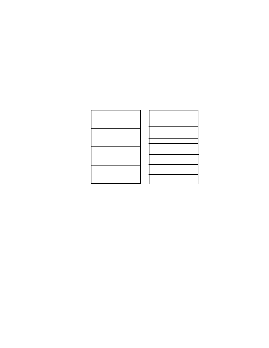
SEGA Confidential
49
User's Guide 2 Graphics Library
[Example 1]
Using Five Screens Displayable by the VDP2
Other than NBG2 and NBG3, all data is bitmap. If rotating screen 1 is
256 colors and the normal 4 screens are 16 colors, it will be as follows.
To move the rotating screen, a rotation parameter table is required. If
X and Y axis rotation is to be done, a rotation parameter coefficient
table must also be prepared.
In this library, the rotation parameter coefficient table is usually
placed at the lead of each bank (VRAM A0, VRAM A1, VRAM B0,
VRAM B1). However, the X and Y axis rotation can only be used in
2kWord (4kByte). This allows the remaining area (124kByte) to be
filled with the rotation parameter table, line scroll table, line color
table, back screen data, etc. (1M bit = 128kByte)
VRAM A0
VRAM A1
VRAM B0
VRAM B1
Rotation Parameter
Coefficienct Table (1word)
256 Colors Bit Map
Data (512x256)1M bit
16 Colors Bit Map Data
(512x256)0.5M bit
Rotation Parameter Table
16 Colors Bit Map Data
(512x256)0.5M bit
Character Parameter
Data Pattern Name Data
Character Parameter
Data Pattern Name Data
RBG 0
NBG 0
NBG 1
NBG 2
NBG3
Figure 2 Using 5 Screens that can be displayed by the VDP2
|

SEGA Confidential
50
[Example 2]
Using 2 Rotation Screens
Only one type of rotation data, such as character data (bitmap data),
pattern name data, rotation parameter coefficient data, etc., can be
placed in each bank. Furthermore, RGB1 placement is fixed with
character pattern data in VRAM B0, and pattern name data is VRAM
B1.
VRAM A0
VRAM A1
VRAM B0
VRAM B1
Rotation Parameter
Coefficienct Table (1word)
256 Colors Bit Map
Data (512x256)1M bit
Rotation Parameter Table
Character Pattern Data
1Mbit
RBG 0
Pattern Name Data
1Mbit
RBG 1
Figure 3 Using 2 Rotation Screens
|

SEGA Confidential
51
User's Guide 2 Graphics Library
Setting VRAM Assignments and Cycle Patterns
VDP2 displays by reading from VRAM at the same time as the scroll screen data is
being scanned on the TV. VRAM access during display is either 4 times (hi-res
display) or 8 times (normal display) being one access unit (1 cycle) with cycles being
repeated.
There is a cycle pattern register prepared for each VRAM and bank, VRAM
A(VRAM A0, VRAM A1) and VRAM B (VRAM B0, VRAM B1). Access is displayed
as 4 bit for one command. (Refer to "3.4 VRAM Access during display in the VDP2
User's Manual").
The number of accesses set in the cycle pattern depends on the data type and use.
These need to be applied to the cycle pattern table.
Table 1 Access count for the required pattern name table data for 1 cycle
For example, with 16 color bitmap data (uses character pattern data), up to four sets
of 512 x 256 data can placed in just one or in either VRAM A or VRAM B. If this is
applied to the normal scroll screen, the access amount would total 4 times. How-
ever, normal scroll screens NBG0 and NBG1 have compression functions. Using this
function and setting the compression ratio to 1/4 would increase the access count to
10, which exceeds 8, and the screen would not be displayed correctly. In this case, if
VRAM allocation is done, the access count will be distributed and the screen will
display correctly.
Item
NBG0 ~ NBG3
RBG0, RBG1
Compression
Times 1
Times 1/2 Times 1/4
VRAM access needed for 1 cycle
1
2
4
8
Table 2 Data Access for character pattern data (bitmap pattern data)
Item
NBG0 ~ NBG3
RBG0, RBG1
TV Display Mode
Normal
Hi-res
Custom
Character colors
16
256
2048
32768
16770000
Compression Rate
1
1/2 1/4
1
1/2
1
1
1
VRAM access needed
for one cycle
1
2
4
2
4
4
4
8
8
4
4
|
SEGA Confidential
52
16 color bitmap data
NBG0 1 times
VRAM A
16 color bitmap data
NBG1 1 times
Character pattern data
Pattern name
NBG2 1 times
Character pattern data
Pattern name
NBG3 1 times
VRAM 0
16 color bitmap data
NBG0 1/4 times
16 color bitmap data
NBG1 1/4 times
VRAM 1
Character pattern data
Pattern name
NBG2 1 times
Character pattern data
Pattern name
NBG3 1 times
Figure 4 16 Color Bitmap Data
Program Examples
Program examples using the C language are shown below.
#include <machine.h>
#include "sega_scl.h"
/* Set the cycle pattern table
*/
Uint16 n0_cycle[]={0x44ff, 0x0fff,/* VRAM A(A0)NBG0 Character pattern
and pattern name table on
*/
0xffff, 0xffff, /* VRAM A1 VRAM A is not allocated so
*/
/* is not used */
0xffff, 0xffff, /* VRAM B(B0) Non Table
*/
0xffff, 0xffff};/* VRAM B1 VRAM B is not allocated so
*/
/* is not used */
extern Uint16 ColData[];
/* Pallet data pointer
*/
SclConfig scfg;
main()
{
SCL_Vdp2Init();
/* Initial VDP2 library
*/
SCL_SetDisplayMode(SCL_NON_INTER, SCL_224LINE, SCL_NOMAL_A);
/* Sets the screen mode
*/
SCL_SetColRamMode(SCL_CRM_2048):
/* Sets the color RAM mode
*/
SCL_AlloColRam(SCL_NBG0, 256, ON);
/* Reserve pallet area
*/
SCL_SetColRam(SCL_NBG0, 0, 265, ColData);
/* Sets the pallet data
*/
|

SEGA Confidential
53
User's Guide 2 Graphics Library
...................
/* Store the scroll data in VDP2 VRAM
*/
SCL_InitConfigTb(&scfg);
/* Initialize scroll NBG0 configuration
*/
scfg.dispenbl = ON;
/* Display NBG0 on the screen
*/
scfg.charsize = SCL_CHAR_SIZE_1X1;
scfg.pnamesize = SCL_PN1WORD;
scfg.platesize = SCL_PL_SIZE_1X1;
scfg.coltype = SCL_COL_TYPE_256;
scfg.flip = SCL_PN_12BIT;
scfg.datatype = SCL_CELL;
scfg.plate_addr[0] = SCL_VDP2_VRAM_A+0x0000;
scfg.plate_addr[1] = SCL_VDP2_VRAM_A+0x2000;
scfg.plate_addr[2] = SCL_VDP2_VRAM_A+0x4000;
scfg.plate_addr[3] = SCL_VDP2_VRAM_A+0x6000;
SCL_SetConfig(SCL_NBG0, &scfg);
SCL_SetPriority(SCL_NBG0, 7); /* Set the priority to maximum
*/
SCL_SetCycleTable(n0_cycle);
/* Set the cycle pattern
*/
INT_SetScuFunc(.....);
/* Record the V-Blank routine
*/
set_imask(0);
/* Enables the interrupt.+
*/
SCL_Open(SCL_NBG0);
/* NBG0 open processing
*/
SCL_Move(FIXED(1), FIXED(1), 0);/* Types of scroll move functions
*/
.
.
.
SCL_Close(SCL_NBG0);
/* End scroll processing
*/
SCL_DisplayFrame();
/* Wait for V-BLANK display scroll
*/
}
|

SEGA Confidential
54
(There is no page 54 in the original Japanese document.)
|

SEGA Confidential
55
User's Guide 2 Graphics Library
2.0
Reference
2.1
Data Specifications
Title
Data
Data Name
No
Data Specification
2D Data Structure
SclXy
typedef struct SclXy {
Fixed32 x;
Fixed32 y;
} SclXy;
Title
Data
Data Name
No
Data Specification
3D Data Structure
SclXyz
typedef struct SclXyz {
Fixed32 x;
Fixed32 y;
Fixed32 z;
} SclXyz;
Title
Data
Data Name
No
Data Specification
Data Structure of the Line Parameter Table
SclLineTb
typedef struct SclLineTb {
Fixed32 h;
/* Horizontal screen scroll value
*/
Fixed32 v;
/* Vertical screen scroll value
*/
Fixed32 dh;
/* Increment of horizontal coordinates
*/
} SclLineTb;
Title
Data
Data Name
No
Data Specification
Data Structure of the line window
SclLinWindowTb
typedef struct SclLinWindowTb {
Uint16 start;
/* Horizontal start point coordinate
*/
Uint16 end;
/* Horizontal end point coordinate
*/
} SclLinWindowTb;
|

SEGA Confidential
56
Title
Data
Data Name
No
Data Specification
Structure of the RGB Color Table Data
SclRgb
typedef struct SclRgb {
Sint16 red;
/* Red
*/
Sint16 green;
/* Green
*/
Sint16 blue;
/* Blue
*/
} SclRgb;
Title
Data
Data Name
No
Data Specification
VRAM Configuration Data Structure
SclVramConfig
typedef struct SclVramConfig {
Uint32
ktboffsetA; /* Indicates the coefficient rotation
*/
/* parameter table in the relative VRAM */
/* address. If SCL_RBG_K is indicated, */
/* the relative address is designated there.
*/
Uint32
ktboffsetB; /* Designated units are 2048 (0x400) byte*/
/* Specified in relative address
*/
Uint8
vramModeA;
/* Separate VRAM A into 2 patterns
*/
/* ON/OFF
*/
Uint8
vramModeB;
/* Separate VRAM B into 2 patterns
*/
/* ON/OFF
*/
Uint8
vramA0;
/* Use VRAM A0 for which rotation screen*/
/* If not separated, uses all of VRAM A */
/* SCL_NON
*/
/*
Do not place rotation data
*/
/* SCL_RBG0_K
*/
/*
Place RBG0 coefficient data
*/
/* SCL_RBG0_PN
*/
/*
Place RGB0n pattern name data
*/
/* SCL_RBG0_CHAR
*/
/*
Place RGB0 character
*/
Uint8
vramA1;
/* Use VRAMA1 for which rotation screen */
/* Invalid if VRAMA is not separated
*/
Uint8
vramB0;
/* Use VRAM B0 for which rotation screen*/
/* If not separated, uses all of VRAM B */
Uint8
vramB1;
/* Use VRAM B1 for which rotation screen*/
/* Invalid if VRAM B is not separated
*/
Uint8
colram;
/* Indicates whether to place coefficient data
*/
/* into color RAM. If coefficient data is
*/
/* placed in VRAM, it can't be used. Unless the*/
/* color RAM mode is SCL_CRM15-2048, it can't */
/* be used. Specified with SCL_RBG0_K or SCL_NON*/
} SclVramConfig;
Note:
If any type of rotation data is placed in a VRAM bank, other data
cannot be placed there. However, if ktboffsetA or ktboffsetB is set, other data can
be placed with coefficient data.
|

SEGA Confidential
57
User's Guide 2 Graphics Library
Title
Data
Data Name
No
Data Specification
Structure of the Scroll Configuration Data
Sclconfig
Refer to the "VDP2 User's Manual" for details on parameter settings.
typedef struct SclConfig {
Uint8
dispenbl;
/* Display ON/OFF
*/
/* Screen display enable register (180020h)
*/
/*
ON Display picture on screen
*/
/*
OFF Do not display picture on screen
*/
Uint8
charsize;
/* Character size
*/
/* Char. control reg.(180028h~18002ah)
*/
/* SCL_CHAR_SIZE_1X1
*/
/*
Set to 1X1
*/
/* SCL_CHAR_SIZE_2x2
*/
/*
Set to 2x2
*/
Uint8
pnamesize
/* Pattern Name Size
*/
/*
Pattern Name Cntrl. reg.(180030h~18038h)
*/
/* SCL_PN2WORD
*/
/*
Set to 2Word units
*/
/* SCL_PN1WORD
*/
/*
Set to 1Word units
*/
Uint8
platesize;
/* Plane Size
*/
/* Plane size register (18003ah)
*/
/* SCL_PL_SIZE_1X1
*/
/*
Set to 1X1
*/
/* SCL_PL_SIZE_2X1
*/
/*
Set to 2X1
*/
/* SCL_PL_SIZE_2X2
*/
/*
Set to 2X2
*/
Uint8
bmpsize;
/* Bitmap size */
/* Char. control reg.(180028h~18002ah)
*/
/* SCL_BMP_SIZE_512X256
*/
/*
Set to 512X256
*/
/* SCL_BMP_SIZE_512X512
*/
/*
Set to 512X512
*/
/* SCL_BMP_SIZE_1024X256
*/
/*
Set to 1024X256
*/
/* SCL_BMP_SIZE_1024X512
*/
/*
Set to 1024X512
*/
Uint8
coltype;
/* Character Colors */
/* Char. control reg.(180028h~18002ah)
*/
/* SCL_COL_TYPE_16
*/
/*
Sets to 16 colors
*/
/* SCL_COL_TYPE_256
*/
/*
Sets to 256 colors
*/
/* SCL_COL_TYPE_2048
*/
/*
Sets to 2048 colors
*/
/* SCL_COL_TYPE_32K
*/
/*
Sets to 32K colors
*/
/* SCL_COL_TYPE_1M
*/
/*
Sets to 16,770,000 colors
*/
Uint8
datatype;
/* Enable
bitmap
*/
/* Char. control reg.(180028h~18002ah)
*/
/* SCL_BITMAP
*/
/*
Set to bitmap format
*/
|

SEGA Confidential
58
/*
SCL_CELL
*/
/*
Sets the cell format
*/
Uint8
mapover;
/* Over screen processing
*/
/* Over screen process register (18003ah)
*/
/* SCL_OVER0
*/
/*
Repeat image that was set as display area */
/*
outside the display area.
*/
/* SCL_OVER1
*/
/*
Repeat pattern designated by the screen
*/
/*
over pattern name register
*/
/*
(Only rotation screen)
*/
/* SCL_OVER_2
*/
/*
Make areas outside of display transparent */
/* SCL_OVER_3
*/
/*
Make the display area 512X512 and make all*/
/*
other areas transparent.
*/
Uint8
flip
/* Character number support mode
*/
/* Designates whether to use special functions */
/* and reverse functions when the pattern name */
/* size is 1Word. If designated, the character */
/* number is 10bit, if not 12bit
*/
/* Pattern Name Cntrl Register (180030h~180038h)*/
/*
SCL_PN_10BIT
*/
/*
Enables special and reverse functions
*/
/*
SCL_PN_12BIT
*/
/*
Disables special and reverse functions */
Uint16 patnamecontrl;
/* Aux data in the pattern name control register*/
Uint32 plate_addr[16];
/* Scroll Screen Map Register
*/
/* If cell format, designates pattern name
*/
/* table lead address
*/
/* If bitmap format, designates bitmap data
*/
/* lead address
*/
/* Normal(180040h~18004eh)
*/
/* Rotate(180050h~18006eh)
*/
} Sclconfig;
|

SEGA Confidential
59
User's Guide 2 Graphics Library
Title
Data
Data Name
No
Data Specification
Structure of line & and vertical cell scroll
parameter data
SclLineParam
Refer to the "VDP2 User's Manual" for details on parameter settings.
typedef struct SclLineParam {
Uint8
delta_enbl;
/* Enable Line Zoom
*/
/* Line & Vertical cell scroll register (18009ah)*/
/* ON/OFF
*/
Uint8
v_enbl;
/* Enable line scroll (perpendicular)
*/
/* Line & Vertical cell scroll register (18009ah)*/
/* ON/OFF
*/
Uint8
h_enbl
/* Enable line scroll (horizontal)
*/
/* Line & Vertical cell scroll register (18009ah)*/
/* ON/OFF
*/
Uint8
cell_enbl;
/* Enable vertical cell scroll
*/
/* Line & Vertical cell scroll register (18009ah)*/
/* ON/OFF
*/
Uint8
interval;
/* Line scroll interval
*/
/* Line & Vertical cell scroll register (18009ah)*/
/* SCL_1_LINE
*/
/*
Sets the line scroll data table every 1 */
/*
line.
*/
/* SCL_2_LINE
*/
/*
Sets the line scroll data table every 2 */
/*
lines.
*/
/* SCL_4_LINE
*/
/*
Sets the line scroll data table every 4 */
/*
lines.
*/
Uint32
line_addr;
/* Line scroll address register(18009ch~18009eh) */
/* Sets the VRAM address for line scroll table
*/
Uint32
cell_addr;
/*
Vert. cell scroll table address register (18009c~18009e)
*/
/* Sets VRAM address for cell scroll table
*/
GlbLineTb
line_tbl[];
/* Line scroll table
*/
Fixed32
cell_tbl[];
/* Vertical cell scroll address register
*/
} SclLineParam;
|

SEGA Confidential
60
Title
Data
Data Name
No
Data Specification
VDP2 Register Buffer 1
SclSysReg
typedef struct SclSysReg {
/* Address contents
*/
Uint16
tvmode;
/* 18000H TV screen mode
*/
Unit16
extenbl;
/* 18002H External signal
*/
Unit16
tvstatus;
/* 18004H Screen status
*/
Unit16
vramsize;
/* 18006H VRAM size
*/
Unit16
H_val;
/* 18008H H counter
*/
Unit16
V_val;
/* 1800AH V counter
*/
Unit16
vramchg;
/* 1800CH
*/
Unit16
ramcontrl;
/* 1800EH RAM control
*/
Unit16
vramcyc[8];
/* 18010H VRAM cycle pattern
*/
Unit16
dispenbl;
/* 18020H Enable screen display
*/
Unit16
mosaic;
/* 18022H Mosaic control
*/
Unit16
specialcode_sel;/* 18024H Select special code
*/
Unit16
specialcode;
/* 18026H Special function control
*/
} SclSysReg;
Symbols are recorded in this library as shown below. After this
symbol is written, and the global variable "SclProcess" has a 1
written to it, then that will be reflected in the register during the
next V-BLANK.
SclSysReg
Scl_s_reg;
Title
Data
Data Name
No
Data Specification
VDP2 Register Buffer 2
SclDataset
typedef struct SclDataset {
/* Address contents
*/
Uint16
charcontrl0;
/* 18028H Charater control (NBG0, NBG1) */
Unit16
charcontrl1;
/* 1802AH Character control (NBG2, NBG3, RBG0) */
Unit16
bmpalnum0;
/* 1802CH Bitmap pallet number (NBG0, NBG1)
*/
Unit16
bmpalnum1;
/* 1802EH Bitmap pallet number (RBG0)
*/
Unit16
patnamecontrl[15]/* 18030H Pattern name control
*/
Unit16
platesize;
/* 1803AH Plane size
*/
Unit16
mapoffset0;
/* 1803CH Map offset (NBG0~NBG3)
*/
Unit16
mapoffset1;
/* 1803EH Map offset (rotate parameter A, B)
*/
Unit16
normap[8];
/* 18040H Map (normal scroll)
*/
Unit16
rotmap[16];
/* 18050H Map (rotate parameter A, B)
*/
} SclDataset;
Symbols are recorded in this library as shown below. After this
symbol is written, and the global variable "SclProcess" has a 1
written to it, then that will be reflected in the register during the
next V-BLANK.
SclDataset
Scl_d_reg;
|

SEGA Confidential
61
User's Guide 2 Graphics Library
Title
Data
Data Name
No
Data Specification
VDP2 Register Buffer 3
SclNorscl
typedef struct SclNorscl {
/* Address contents
*/
Fixed32 n0_move_x;
/* 18070H H screen scroll value (NBG0)
*/
Fixed32 n0_move_y;
/* 18074H V screen scroll value (NBG0)
*/
Fixed32 n0_delta_x;
/* 18078H H coordinate increase (NBG0)
*/
Fixed32 n0_delta_y;
/* 1807CH V coordinate increase (NBG0)
*/
Fixed32 n1_move_x;
/* 18080H H screen scroll value (NBG1)
*/
Fixed32 n1_move_y;
/* 18084H V screen scroll value (NBG1)
*/
Fixed32 n1_delta_x;
/* 18088H H coordinate increase (NBG1)
*/
Fixed32 n1_delta_y;
/* 1808CH V coordinate increase (NBG1)
*/
Uint16
n2_move_x;
/* 18090H H screen scroll value (NBG2)
*/
Unit16
n2_move_y;
/* 18092H V screen scroll value (NBG2)
*/
Unit16
n3_move_x;
/* 18094H H screen scroll value (NBG3)
*/
Unit16
n3_move_y;
/* 18096H V screen scroll value (NBG3)
*/
Unit16
zoomenbl;
/* 18098H Enable compression
*/
Unit16
linecontrl;
/* 1809AH line & V cell cntrl (NBG0, NBG1)
*/
Unit16
celladdr;
/* 1809CH V cell scroll tbl addr (NBG0, NBG1) */
Unit16
lineaddr[2];
/* 180A0H Line control table address
*/
Unit16
linecolmode;
/* 180A8H Line color screen table address*/
Unit16
backcolmode;
/* 180ACH Back screen table address
*/
} SclNorscl;
Symbols are recorded in this library as shown below. After this
symbol is written, and the global variable "SclProcess" has a 1
written to it, then that will be reflected in the register during the
next V-BLANK.
SclNorscl
Scl_n_reg;
Title
Data
Data Name
No
Data Specification
VDP2 Register Buffer 4
SclRotscl
typedef struct SclRotsel {
/* Address contents
*/
Uint16
paramode;
/* 1800B0H Rotate parameter mode
*/
Unit16
paramcontrl;
/* 1800B2H Rotate parameter list control*/
Unit16
k_contrl;
/* 1800B4H Coefficient table control
*/
Unit16
k_offset;
/* 1800B6H Coefficient table address offset
*/
Unit16
mapover[2]
/* 1800B8H Screen over pattern name
*/
Unit16
paramaddr;
/* 1800BAH Rotate parameter table address*/
} SclRotsel;
Symbols are recorded in this library as shown below. After this
symbol is written, and the global variable "SclProcess" has a 1
written to it, then that will be reflected in the register during the
next V-BLANK.
SclRotscl
Scl_r_reg;
|

SEGA Confidential
62
Title
Data
Data Name
No
Data Specification
VDP2 Register Buffer 5
SclWinscl
typedef struct SclWinscl {
/* Address contents
*/
Uint16
win0_start[2];
/* 1800C0H Window position (w0, start XY) */
Unit16
win0_end[2];
/* 1800C4H Window position (w0, end XY)
*/
Unit16
win0_start[2];
/* 1800C8H Window position (w0, start XY) */
Unit16
win0_end[2];
/* 1800CCH Window position (w0, end XY)
*/
Unit16
wincontrl940;
/* 1800D0H Window control
*/
Unit16
linewin0_addr;
/* 1800D8H
Line Window table address (W0)*/
Unit16
linewin1_addr;
/* 1800DCH
Line Window table address (W0)*/
} SclWinscl;
Symbols are recorded in this library as shown below. After this
symbol is written, and the global variable "SclProcess" has a 1
written to it, then that will be reflected in the register during the
next V-BLANK.
SclWinscl
Scl_w_reg;
Title
Data
Data Name
No
Data Specification
XY Size of screens used in the library
SclDisplayX, SclDisplayY
This is a 2Byte global variable. When this variable is referenced, the
display vertical and horizontal size changes. By using the library
and setting the display mode, this can automatically be reflected.
Uint16
SclDisplayX;
Uint16
SclDisplayY;
|

SEGA Confidential
63
User's Guide 2 Graphics Library
2.2 List of Functions
Function
Function Name
Number
[Initializing Functions]
Initialize Library
SCL_Vdp2Init
1
[Table Creation and Data Set Functions]
Set display mode
SCL_SetDisplay Mode
2
Initialize VRAM configuration data table
SCL_InitVramConfigTb
3
Initialize scroll configuration data table
SCL_InitConfigTb
4
Set the VDP2 VRAM usage method
SCL_SetVramConfig
5
Set the scroll configuration
SCL_SetConfig
6
Set cycle patterns
SCL_SetCycleTable
7
[Functions Related to the Display Screen Functions]
Scroll open process
SCL_Open
8
Scroll close process
SCL_Close
9
Initialize line and vertical cell scroll parameter table
SCL_InitLineParamTb
10
Set line and vertical cell scroll parameters
SCL_SetLineParam
11
Move scroll (Amount of move : absolute coord.)
SCL_MoveTo
12
Move scroll (Amount of move : relative coord.)
SCL_Move
13
Enlarge or reduce scroll
SCL_Scale
14
Initialize the rotation parameter table
SCL_InitRotateTable
15
Set rotation view
SCL_SetRotateViewPoint
16
Set the display rotate center coordinates
SCL_SetRotateCenterDisp
17
Set rotation center
SCL_SetRotateCenter
18
Scroll rotate (angle : absolute coord.)
SCL_RotateTo
19
Scroll rotate (angle : relative coord.)
SCL_Rotate
20
Set scale coefficient data in the rotate coefficient table
SCL_SetCoefficientData
21
Set mosaic process
SCL_SetMosaic
22
[Line Screen Setting Functions]
Set line color screen data
SCL_SetLncl
23
Set back screen data
SCL_SetBack
24
[Window Setting Functions]
Set normal rectangle window
SCL_SetWindow
25
Set normal line window
SCL_SetLineWindow
26
Set sprite window
SCL_SetSpriteWindow
27
|

SEGA Confidential
64
Function
Function Name
Number
[Functions Related to VDP1]
Set different sprite modes
SCL_SetSpriteMode
28
[Functions Related to Color RAM]
Set color RAM mode
SCL_SetColRamMode
29
Get color RAM mode
SCL_GetColRamMode
30
Set color RAM color data
SCL_SetColRamCol
31
Allocate area for color RAM
SCL_AllocColRam
32
Free area allocated for color RAM
SCL_FreeColRam
33
Set auto color change
SCL_SetAutoColChg
34
Get the color RAM address offset
SCL_GetColRamOffset
35
[Functions Related to Priority]
Set priorities
SCL_SetPriority
36
Get priorities
SCL_GetPriority
37
[Functions Related to Color Calculations]
Set color calculation conditions (SPRITE)
SCL_SetColMixMode
38
Set color calculation mix
SCL_SetColMixRate
39
Set auto color calculation
SCL_SetAutoColMix
40
[Functions Related to Color Offset]
Set color offset
SCL_SetColOffset
41
Increase and decrease the color offset value
SCL_IncColOffset
42
Set the auto color offset
SCL_SetAutoColOffset
43
[Other Special Effect Functions]
Enable blur calculations
SCL_EnableBlur
44
Disable blur calculations
SCL-DisableBlur
45
Enable line color screen
SCL_EnableLineCol
46
Disable line color screen
SCL_DisableLineCol
47
Set shadow bit
SCL_SetShadowBit
48
[Functions Related to V-BLANK Interrupt Processing]
Set frame change interval count
SCL_SetFrameInterval
49
Wait for frame change request to end
SCL_DisplayFrame
50
V-BLANK start VDP interrupt processing
SCL_VblankStart
51
V-BLANK end VDP interrupt processing
SCL_VblankEnd
52
[Abort Function]
Force abort of automatic VE
SCL_AborAutoVe
53
|

SEGA Confidential
65
User's Guide 2 Graphics Library
2.3
Function Specifications
Title
Function
Function Name
No
Function Specification
Initialize library
SCL_Vdp2Init
1
Format
void SCL_Vdp2Init(void)
Input
None
Output
None
Function Value
None
Function
Initializes the library. This command must be executed once
before using the library.
Title
Function
Function Name
No
Function Specification
Set display mode
SCL_SetDisplayMode
2
Format
voi d SCL_Set Di spl ayMode(Ui nt 8 i nt e rl ace, Ui nt 8 ve rt i cal , Ui nt 8
ho ri zont al )
Input
interlace
: Interlace mode setting
SCL_NON_INTER
: Noninterlace
SCL_SINGLE_INTER
: Single interlace
SCL_DOUBLE_INTER
: Double interlace
vertical
: Vertical resolution bit
SCL_224LINE
: 224 lines
SCL_240LINE
: 240 lines
SCL_256LINE
: 256 lines
horizontal : Horizontal resolution bit
SCL_NORMAL_A
: 320 Pixels
: Normal Graphic A
SCL_NORMAL_B
: 352 Pixels
: Normal Graphic B
SCL_HIRESO_A
: 640 Pixels
: Hi-res Normal Graphic A
SCL_HIRESO_B
:704 Pixels
: Hi-res Normal Graphic B
SCL_NORMAL_AE
: 320 Pixels
: Custom Normal Graphic A
SCL_NORMAL_BE
: 352 Pixels
: Custom Normal Graphic B
SCL_HIRESO_AE
: 640 Pixels
: Custom Hi-res Graphic A
SCL_HIRESO_BE
: 704 Pixels
: Custom HIi-res Graphic B
Output
None
Function Value
None
Function
Sets the display mode.
Comments
When changing the horizontal resolution from A to B, SH2
clock changes from 76 to 78. (Example: SCL_NORMAL)A
SCL_NORMAL_B) Be careful because VDP1 and VDP2 settings
are reset at this time.
|

SEGA Confidential
66
Title
Function
Function Name
No
Function Specification
Initialize VRAM configuration table
SCL_InitVramConfigTb
3
Format
void SCL_InitVramConfigTb(SclVramConfig *tp)
Input
tp
: VRAM configuration table
Output
None
Function Value
None
Function
Writes the default values to the VRAM configuration table.
Title
Function
Function Name
No
Function Specification
Initialize scroll configuration data
table
SCL_InitConfigTb
4
Format
void SCL_InitConfigTb(SclConfig *scfg)
Input
scfg
: Scroll configuration data
Output
None
Function Value
None
Function
Initializes the scroll configuration data table.
Title
Function
Function Name
No
Function Specification
Set the VDP2 VRAM usage method
SCL_SetVramConfig
5
Format
void SCL_SetVramConfig(SclVramConfig *tp)
Input
tp
: VRAM configuration table.
Output
None
Function Value
None
Function
Sets the VDP2 VRAM usage method.
Example
Allocates VRAM B; each bank is identified for RBG0 character
and pattern name data.
sample()
{
SclVramConfig tp;
SCL_InitVramConfigTb(&tp);
tp.vramModeB = ON
/* Allocates VRAM B for use
*/
tp.vramB0 = SCL_RBG0_CHAR; /* Places RBG0 character data
*/
tp.vramB1 = SCL_RBG0_PN;
/* Places RBG0 pattern name data
*/
SCL_SetVramConfig(&tp);
}
|

SEGA Confidential
67
User's Guide 2 Graphics Library
Title
Function
Function Name
No
Function Specification
Set the scroll configuration
SCL_SetConfig
6
Format
void SCL_SetConfig(Uint16 sclnum, SclConfig *scfg)
Input
sclnum :
scroll screen number
Select one of six screens SCL_NBG0, SCL_NBG1,
SCL_NBG2, SCL_NBG3, SCL_RBG0, SCL_RBG1
scfg
:
Scroll configuration table pointer
Output
None
Function Value
None
Function
Sets the scroll configuration.
Comments
When setting rotation screen data, the SCL_IntRotateTable()
must be run first.
Title
Function
Function Name
No
Function Specification
Set VRAM cycle pattern table
SCL_SetCycleTable
7
Format
void SCL_SetCycleTable(Uint16 *tp)
Input
tp
: Cycle pattern table
Output
None
Function Value
None
Function
Sets the cycle pattern table.
Comments
If the cycle pattern table is not set correctly, the normal scroll
screen will not display properly. It is advised to have an
understanding of Chapter 3 RAM, "3.4 VRAM Access Methods
During Display Intervals" in the VDP2 User's Manual.
Example 1
Image
: NBG0 256 colors (with 1/2 scale display)
VRAM A: Places the NBG0 character pattern data.
VRAM B : Places the NBG0 pattern name table.
Uint16 cycle[] = {
/* Cycle pattern table
*/
0x4444, 0xffff,
/* VRAM A(A0)
*/
0xffff, 0xffff,
/* VRAM A1 Not used
*/
0x00ff, 0xffff,
/* VRAM B(B0)
*/
0xffff, 0xffff,
/* VRAM B1 Not used
*/
}
sample()
{
SCL_SetCycleTable(&cycle);
}
|

SEGA Confidential
68
Example 2
Image
: NBG0 16.77 million colors bitmap data
VRAM A: Places the NBG0 bitmap data.
VRAM B : Places the NBG0 bitmap data.
Uint16 cycle[] = {
/* Cycle pattern table
*/
0x4444, 0x4444,
/* VRAM A(A0)
*/
0xffff, 0xffff,
/* VRAM A1 Not used
*/
0x4444, 0x4444,
/* VRAM B(B0)
*/
0xffff, 0xffff,
/* VRAM B1 Not used
*/
}
sample()
{
SCL_SetCycleTable(&cycle);
}
Example 3
Image
: RBG0 256 color bitmap data
NBG0 16 colors bitmap data (1/4 reduced)
NBG1 16 colors bitmap data (1/2 reduced)
NBG2 16 colors character data / pattern name data
NBG3 16 colors character data / pattern name data
VRAM A0 : Places the RBG0 bitmap data.
VRAM A1 : Places the rotate parameter coefficient table.
Places the rotate parameter table.
VRAM B0 : Places the NBG0 bitmap data.
Places the NBG1 bitmap data.
VRAM B1 : Places NBG2 character and pattern name data
Places NBG3 character and pattern name data
Uint16 cycle[] = {
/* Cycle pattern table
*/
0xffff, 0xffff,
/* VRAM A0
*/
0xffff, 0xffff,
/* VRAM A1
*/
0x4444, 0xff55,
/* VRAM B0
*/
0x23ff, 0x67ff,
/* VRAM B1
*/
}
sample()
{
SCLVramConfig tp;
SCL_InitVramConfigTb(&tp);
tb.vramModeA = ON
/* Allocate and use VRAM A
*/
tp.vramA0 = SCL_RBG0_CHAR;
/* Place RBG0 bitmap data
*/
tp.vramA1 = SCL_RGB0_K;
/* Place rotate coeff. param.tbl. */
SCL_SetVramConfig(&tp);
SCL_SetCycleTable(&cycle);
}
|

SEGA Confidential
69
User's Guide 2 Graphics Library
Title
Function
Function Name
No
Function Specification
Scroll open process
SCL_Open
8
Format
void SCL_Open(Uint32 sclnum)
Input
sclnum : Select the scroll screen number or 4 rotate parameter
table normal screens (SCL_NBG0, SCL_NBG1,
SCL_NBG2, SCL_NBG3), or rotate parameter table
A, B (SCL_RBG_TB_A, SCL_RBG_TB_B).
Output
None
Function Value
None
Function
Depending on the scroll screen selected, the following
functions become available for use.
SCL_SetLineParam SCL_Move
SCL_MoveTo
SCL_Scale
SCL_Rotate SCL_RotateTo
Title
Function
Function Name
No
Function Specification
Scroll close process
SCL_Close
9
Format
void SCL_Close(void)
Input
None
Output
None
Function Value
None
Function
Closes the functions selected with SclOpen().
Title
Function
Function Name
No
Function Specification
Initialize line and vertical cell scroll parameter
table
SCL_InitLineParamTb
10
Format
void SCL_InitLineParamTb(SclLineParam *lp)
Input
lp
: Line & vertical scroll parameter data
Output
None
Function Value
None
Function
Initializes the line and cell scroll parameter table.
|

SEGA Confidential
70
Title
Function
Function Name
No
Function Specification
Set line and vertical cell scroll
parameters
SCL_SetLineParam
11
Format
void SCL_SetLineParam(SclLineParam *lp)
Input
lp
: Line parameter table
Output
None
Function Value
None
Function
None
Remarks
Runs from the time that SclOpen() is executed until SclClose()
is executed. It can only set NBG0, NBG1.
Title
Function
Function Name
No
Function Specification
Move scroll (Amount of move :
absolute coord.)
SCL_MoveTo
12
Format
void SCL_MoveTo(Fixed32 x, Fixed32 y, Fized32 z)
Input
Indicates the coordinates of where to put the scroll screen.
x : X coordinates
y : Y coordinates
z : Z coordinates
Output
None
Function Value
None
Function
Moves the scroll to absolute coordinates
Remarks
Runs from the time that SclOpen() is executed until SclClose()
is executed. The Z coordinate can only be used with the rotate
parameter table.
Title
Function
Function Name
No
Function Specification
Move scroll (Amount of move :
relative coord.)
SCL_Move
13
Format
void SCL_Move(Fixed32 x, Fixed32 y, Fized32 z)
Input
x : Indicates move distance in X direction
y : Indicates move distance in Y direction
z : Indicates move distance in Z direction
Output
None
Function Value
None
Function
Moves the scroll relatively
Remarks
Runs from the time that SclOpen() is executed until SclClose()
is executed. The Z coordinate can only be used with the rotate
parameter table.
|

SEGA Confidential
71
User's Guide 2 Graphics Library
Title
Function
Function Name
No
Function Specification
Enlarge or reduce scroll
SCL_Scale
14
Format
void SCL_Scale(Fixed32 sx, Fixed32 sy)
Input
sx
: Size designation in the X direction
sy
: Size designation in the Y direction
NBG0, NBG1
: 1/4~256
RBG0, RBG1
: Free
Output
None
Function Value
None
Function
Scales the scroll screen.
Comments
Runs from the time that SclOpen() is executed until SclClose()
is executed. NBG2, NBG3 cannot be used.
Title
Function
Function Name
No
Function Specification
Initialize the rotation parameter table
SCL_InitRotateTable
15
Format
Uint32 SCL_InitRotateTable(Uint32 address, Uint16 num,
Uint32 rotateA, Uint32 rotateB)
Input
address : Indicates the address to place the rotate parameter
table.
num
: Table Count
1 : Only uses rotate parameter A
2 : Uses rotate parameters A and B
rotateA : Select what to display using rotate parameter A.
SCL_SPR
: Only display the sprite frame buffer
SCL_RBG0 : Display RBG0 and sprite frame buffer
SCL_NON : Do not display
rotateB : Select what to display using rotate parameter B.
SCL_RBG0 : Display RBG0
SCL_RBG1 : Display RBG1
SCL_ NON : Do not display
Output
None
Function Value
0: Normal
1: Misallocation
2: Contradictions in the settings
Function
Initializes the rotate parameter table and sets which location in
VRAM to place the rotate parameter table.
Comments
When using both rotate parameter tables A and B, screen
repetition, XY axis rotate combination and Y axis rotation will
not display correctly unless window display is designated.
|

SEGA Confidential
72
Title
Function
Function Name
No
Function Specification
Set rotation view
SCL_SetRotateViewPoint
16
Format
void SCL_SetRotateViewPoint(Uint16 x, Uint16 y, Uint16 z)
Input
x : X coordinates
y : Y coordinates
z : Z coordinates
Output
None
Function Value
None
Function
Sets the rotate viewpoint.
Comments
Runs from the time that SclOpen() is executed until SclClose()
is executed. SCL_NBG0~3 cannot be used.
Title
Function
Function Name
No
Function Specification
Set rotation center
SCL_SetRotateCenter
17
Format
void SCL_SetRotateCenterDisp(Uint16 x, Uint16 y)
Input
x : X coordinates
y : Y coordinates
z : Z coordinates
Output
None
Function Value
None
Function
Sets the rotate center point.
Comments
Runs from the time that SclOpen() is executed until SclClose()
is executed. SCL_NBG0~3 cannot be used.
Title
Function
Function Name
No
Function Specification
Set the display rotate center coordinates
SCL_SetRotateCenterDisp
18
Format
void SCL_SetRotateCenter(Uint16 x, Uint16 y, Uint16 z)
Input
x : X coordinates
y : Y coordinates
Output None
Function Value
None
Function
Sets the display rotate center point.
Comments
Runs from the time that SclOpen() is executed until SclClose()
is executed. SCL_NBG0~3 cannot be used.
|

SEGA Confidential
73
User's Guide 2 Graphics Library
Title
Function
Function Name
No
Function Specification
Scroll rotate (angle : absolute coord.)
SCL_RotateTo
19
Format
void SCL_RotateTo(Fixed32 angelXy, Fixed32 angleZ, Fixed32
angleD, Uint16 mode)
Input
angelXy : Sets the X axis or Y axis angle
angleZ
: Sets the Z axis angle
angleD : Sets the screen rotate angle
mode
: Rotate mode. Sets which axis, X or Y, to enable as
the first argument.
SCL_X_AXIS : Rotate scroll X axis.
SCL_Y_AXIS : Rotate scroll Y axis. (Can't use with
RBG1 screen designation.)
Output
None
Function Value
None
Function
Rotate scroll screen.
Comments
Runs from the time that SclOpen() is executed until SclClose()
is executed. SCL_NBG0~3 cannot be used.
Title
Function
Function Name
No
Function Specification
Scroll rotate (angle : relative coord.)
SCL_Rotate
20
Format
void SCL_Rotate(
Fi xed32 angel Xy, Fi xed32 angl eZ, Fi xed32 angl eD)
Input
angelXy : Sets the X axis or Y axis angle increase
angleZ
: Sets the Z axis angle increase
angleD : Sets the screen rotate angle increase
Output
None
Function Value
None
Function
Rotates the rotate scroll screen.
Comments
Runs from the time that SclOpen() is executed until SclClose()
is executed. SCL_NBG0~3 cannot be used.
|
SEGA Confidential
74
Title
Function
Function Name
No
Function Specification
Set scale coefficient data in the rotate
parameter coefficient table
SCL_SetCoefficientData
21
Format
void SCL_SetCoefficientData(Uint32, surface, Uint16
*datap, Uint16 x, Uint16 y)
Input
surface : Indicates which rotate parameter table to use for
data set. (SCL_RBG_TB_A, SCL_RBG_TB_B)
datap
: Data table pointer.
x
: X data size
y
: Y data size
Output
None
Function Value
None
Function
Sets scale coefficient data into the rotate coefficient table.
Title
Function
Function Name
No
Function Specification
Set mosaic process
SCL_SetMosaic
22
Format
void SCL_SetMosaic(Uint32 surface, Uint8 x, Uint8 y)
Input
surface: Screen Type
SCL_NBG0 | SCL_NBG1 |SCL_NBG2 | SCL_NBG3 |
SCL_RBG0 | SCL_RBG1
x :
Horizontal size of the mosaic (0~15, 0 is mosaic off)
y :
Vertical size of the mosaic (0~15)
Cannot set for rotate surface (RBG0, RBG1).
Output
None
Function Value
None
Function
Sets the mosaic functions for each screen.
Comment
If the mosaic process is used, the vertical cell scroll function
cannot be used.
|
SEGA Confidential
75
User's Guide 2 Graphics Library
Title
Function
Function Name
No
Function Specification
Set line color screen data
SCL_SetLncl
23
Format
void SCL_Lncl(Uint32 address, Uint16 tbsize, Uint16
*palNumTb)
Input
address
: Location in VRAM to place the line color table
tbsize
: Indicates the size of the table
PalNumTb : Indicates each line data with the palette number.
16 color
0~15
256 colors
0~255
2048 colors
0~2047
Output
None
Function Value
None
Function
Sets the line color screen data.
Comments
Set the pallet data into color RAM using the SCL_AllocRam()
and SCL_SetColRam() beforehand.
Title
Function
Function Name
No
Function Specification
Set back screen data
SCL_SetBack
24
Format
void SCL_SetBack(
Ui nt 32 address, Ui nt 16 dat aSi ze, Ui nt 16 *dat aTb)
Input
address : Location in VRAM to place the line color table
dataSize : Indicates the number of data tables
dataTb
: Indicates each line data in 5bitRGB.
Output
None
Function Value
None
Function
Sets the back screen data and address.
Example
Sets back screen address in VRAM and sets the color to black.
void sample(void)
{
Uint16 DataTB;
DataTB = 0x0000;
/* Black */
SCL_SetBack(SCL_VDP2_VRAM, 1, &DataTB);
}
|

SEGA Confidential
76
Title
Function
Function Name
No
Function Specification
Set normal rectangle window
SCL_SetWindow
25
Format
void SCL_SetWindow
( Ui nt 8 wi n, Ui nt 32 l ogi c, Ui nt 32 enabl e, Ui nt 32
ar ea, Ui nt 16 st ar t X, Ui nt 16 st ar t Y, Ui nt 16 endX, Ui nt 16 endY)
Input
win
: Indicates the type of window.
SCL_W0: Indicates a W0 window
SCL_W1: Indicates a W1 window
logic
: Here, layering of multiple windows on the screen is
processed by AND. Default is OR.
enable
: Indicates the screen to display the window on.
area
: Indicates use of the outside area of a window,
default is inside area.
The variables logic, enable and area can be calculated together
by using OR.
Constant
logic enable
area
Meaning
SCL_NBG0
Transparent process window NBG0
SCL_NBG1
Transparent process window NBG1
SCL_NBG2
Transparent process window NBG2
SCL_NBG3
Transparent process window NBG3
SCL_RBG0
Transparent process window RBG0
SCL_RBG1
Transparent process window RBG1
SCL_EXBG
Transparent process window EXBG
SCL_SPR
Transparent process window sprite
SCL_RP
Rotate parameter window
SCL_CC
Color calculation window
SCL_NON
Not indicated
: Can be designated
: Cannot be designated on a sprite window
startX
: Rectangle data start point X coordinate
startY
: Rectangle data start point Y coordinate
endX
: Rectangle data end point X coordinate
endY
: Rectangle data end point Y coordinate
Output
None
Function Value None
Function
Sets normal rectangle windows.
|

SEGA Confidential
77
User's Guide 2 Graphics Library
Title
Function
Function Name
No
Function Specification
Set normal line window
SCL_SetLineWindow
26
Format
void SCL_SetLineWindow
( Ui nt 8 wi n, Ui nt 32 l ogi c, Ui nt 32 enabl e,
Ui nt 32 a rea, Ui nt 32 address, Ui nt 32 sy, Ui nt 32 t bSi ze, Sc l Li nW
i ndowTb
*t b)
Input
win
: Indicates the type of window
SCL_W0: Indicates a W0 window
SCL_W1: Indicates a w1 window
logic
: Here, layering of multiple windows on the screen is
processed by AND. Default is OR.
enable
: Indicates the screen to display the window on.
area
: Indicates use of the outside area of a window,
default is inside area.
address : Location of the line window table in VRAM.
sy
: Lead Y coordinate.
tbSize
: Size of the line window table
tb
: Line window table pointer
The variables logic, enable and area can be calculated together
by using OR.
Output
None
Function Value
None
Function
Sets normal line window.
Title
Function
Function Name
No
Function Specification
Set sprite window
SCL_SetSpriteWindow
27
Format
void SCL_SetSpriteWindow
( Ui nt 32 l ogi c, Ui nt 32 enabl e, Ui nt 32
a rea)
Input
logic
: Here, layering of multiple windows on the screen is
processed by AND. Default is OR.
enable
: Indicates the screen to display the window on.
area
: Indicates use of the outside area of a window,
default is inside area.
The variables logic, enable and area can be calculated together
by using OR.
Output
None
Function Value
None
Function
Sets the sprite line window.
Comments
Sprites for the window must be prepared in advance using
VDP1.
|

SEGA Confidential
78
Title
Function
Function Name
No
Function Specification
Set different sprite modes
SCL_SetSpriteMode
28
Format
void SCL_SetSpriteMode
( Ui nt 8 t ype, Ui nt 8 col Mode, Ui nt 8 wi nMode)
Input
type
: Sprite type
SCL_SPR_TYPE0, SCL_SPR_TYPE1 . . . SCL_SPR_TYPEF
colMode : Color mode
SCL_PALETTE, SCL_MIX
(SCL_MIX: palette and RGB mixture)
winMode: Window mode
SCL_MSB_SHADOW, SCL_SP_WINDOW
Output
None
Function Value
None
Function
Sets the sprite type.
Title
Function
Function Name
No
Function Specification
Set color RAM mode
SCL_SetColRamMode
29
Format
void SCL_SetColRamMode(Uint32 mode)
Input
mode
: Color RAM mode
SCL_CRM15_1024, SCL_CRM15_2048, SCL_CRM24_1024
Output
None
Function Value
None
Function
Sets the color RAM mode.
Title
Function
Function Name
No
Function Specification
Get color RAM mode
SCL_GetColRamMode
30
Format
Uint32 SCL_GetColRamMode(void)
Input
None
Output
None
Function Value
Color RAM mode
SCL_CRM15_1024, SCL_CRM15_2048, SCL_CRM24_1024
Function
Sets the color RAM mode.
|

SEGA Confidential
79
User's Guide 2 Graphics Library
Title
Function
Function Name
No
Function Specification
Set color RAM color data
SCL_SetColRam
31
Format
void SCL_SetColRam(Uint32 surface, Uint32 index, Uint32
num, void *color)
Input
surface : Screen type
SCL_SPR, SCL_NBG0, SCL_NBG1, SCL_NBG2, SCL_NBG3,
SCL_RBG0, SCL_RBG1, SCL_LNCL
index
: Write start palette number
num
: Size of the color data table
color
: Color data table (Unit 32 or Unit 16)
Output
None
Function Value
None
Function
Sets color data into the color RAM.
Comments
If using color RAM commonly, you can set just one of the
screens if desired.
Title
Function
Function Name
No
Function Specification
Allocate area for color RAM
SCL_AlllocColRam
32
Format
Uint32 SCL_AllocColRam(Uint32 surface, Uint32 numOfColors,
Uint8 transparent)
Input
surface : Screen type
SCL_SPR | SCL_NBG0 | SCL_NBG1 | SCL_NBG2| SCL_NBG3|
SCL_RBG0| SCL_RBG1| SCL_LNCL
Use OR calculation to use the same palette for multiple screens.
numOfColors: Number of colors
transparent:
Sets whether to use transparent or not.
ON
Palette 0 is not transparent
OFF Palette 0 is transparent
Output
None
Function Value
The lead allocated address
Function
Allocates the color RAM area.
Title
Function
Function Name
No
Function Specification
Free area allocated for color RAM
SCL_FreeColRam
33
Format
void SCL_FreeColRam(Uint32 surface)
Input
surface : Screen type
SCL_SPR | SCL_NBG0 | SCL_NBG1 | SCL_NBG2 | SCL_NBG3 |
SCL_RBG0 | SCL_RBG1
Use OR calculation to use the same palette for multiple screens.
Output
None
Function Value
None
Function
Frees the area allocated for color RAM.
|

SEGA Confidential
80
Title
Function
Function Name
No
Function Specification
Set auto color change
SCL_SetAutoColChg
34
Format
void SCL_SetAutoColChg
( Ui nt 32 sur f ace, Ui nt 32 i nt e rval , Ui nt 32
i ndex, Ui nt 32 numOf Col , Ui nt 32 numOf Tbl , Ui nt 32 changeTbl [ ] )
Input
surface : Screen type
SCL_SPR, SCL_NBG0, SCL_NBG1, SCL_NBG2, SCL_NBG3,
SCL_RBG0, SCL_RBG1
interval : Interval
designated in units of 1/60th of a second
index
: Start palette number to be changed
numOfCol: Number of colors
numOfTbl: Number of Tables
changeTbl[]: Change tables
Output
None
Function Value
None
Function
Changes a portion of each pallet a little at a time towards a
specific color. The number of pallets is limited to 256 colors. It
is not compatible with 2048, or 1024 colors.
Title
Function
Function Name
No
Function Specification
Get the color RAM address offset
SCL_GetColRamOffset
35
Format
Uint32 = SCL_GetColRamOffset(Uint32 surface)
Input
surface : Screen type
SCL_SPR, SCL_NBG0, SCL_NBG1, SCL_NBG2, SCL_NBG3,
SCL_RBG0, SCL_RBG1
Output
None
Function Value
Offset address from the VDP2 VRAM.
Function
Gets the color RAM address offset.
Title
Function
Function Name
No
Function Specification
Set priorities
SCL_SetPriority
36
Format
void SCL_SetPriority(Uint32 surface, Uint8 priority)
Input
surfaces
: Screen types
SCL_SP0|SCL_SP1. . . SCLSP7|SCL_NBG0|SCL_NBG1|
SCL_NBG2| SCL_NBG3| SCL_RBG0|SCL_RBG1|SCL_EXBG
priority : Priority number
Output
None
Function Value
None
Function
Sets the priority.
|

SEGA Confidential
81
User's Guide 2 Graphics Library
Title
Function
Function Name
No
Function Specification
Get priorities
SCL_GetPriority
37
Format
Uint8 Priority = SCL_GetPriority(Uint32 surface)
Input
surfaces :
Screen types
SCL_SPR, SCL_NBG0, SCL_NBG1, SCL_NBG2, SCL_NBG3,
SCL_RBG0, SCL_RBG1, SCL_EXBG
priority : Priority number
Output
None
Function Value
None
Function
Gets the priority.
Title
Function
Function Name
No
Function Specification
Set color calculation conditions (SPRITE)
SCL_SetColMixMode
38
Format
void SCL_SetColMixMode(Uint32 colMixPriority, Uint8 mode)
Input
colMixPriority : Sprite priority number
0~7
mode
: Mode
SCL_IF_FRONT, SCL_IF_EQUAL, SCL_IF_BEHIND
Output
None
Function Value
None
Function
Sets the color calculation conditions.
Title
Function
Function Name
No
Function Specification
Set color calculation mix
SCL_SetColMixRate
39
Format
void SCL_SetColMixRate(Uint32 surfaces, Uint8 rate)
Input
surfaces : Screen types
SCL_SP0|SCL_SP1. . . SCL_SP7|SCL_NBG0|SCL_NBG1|
SCL_NBG2| SCL_NBG3| SCL_RBG0,|SCL_RBG1|SCL_EXBG
Use OR calculation to use the same palette for multiple screens
rate
: Rate
0~31
Output
None
Function Value
None
Function
Sets the color calculation rate.
|

SEGA Confidential
82
Title
Function
Function Name
No
Function Specification
Set auto color calculation
SCL_SetAutoColMix
40
Format
void SCL_SetAutoColMix(Uint32 surfaces, Uint32 interval,
Uint32 time, uint8 startRate, Uint8 endRate)
Input
surfaces : Screen types
SCL_SP0|SCL_SP1. . . SCL_SP7|SCL_NBG0|SCL_NBG1|
SCL_NBG2| SCL_NBG3| SCL_RBG0,|SCL_RBG1|SCL_EXBG
Use OR calculation to use the same palette for multiple screens
interval
: Interval
Designated in units of 1/60th of a second.
time
: Indicates the time to complete the color change.
Designated in units of 1/60th of a second.
startRate : Rate at the starting point
endRate
: Rate at the ending point
Output
None
Function Value
None
Function
Changes the color mix according the designated time or
interval.
Title
Function
Function Name
No
Function Specification
Set color offset
SCL_SetColOffset
41
Format
void SCL_SetColOffset(Uint32 offsetreg, Uint32 surfaces,
Sint16 red, Sint16 green, Sint16 blue)
Input
offsetreg :
Indicates which color offset register to use.
SCL_OFFSET_A, SCL_OFFSET_B
surfaces : Screen types
SCL_SP0|SCL_SP1. . . SCL_SP7|SCL_NBG0|SCL_NBG1|
SCL_NBG2| SCL_NBG3| SCL_RBG0|SCL_RBG1|SCL_EXBG
Use OR calculation to use the same palette for multiple screens
Red
: Color indicator (red)
green : Color indicator (green)
blue
: Color indicator (blue)
Output
None
Function Value
None
Function
Sets the color offset.
|

SEGA Confidential
83
User's Guide 2 Graphics Library
Title
Function
Function Name
No
Function Specification
Increase/decrease the color offset
value
SCL_IncColOffset
42
Format
void SCL_IncColOffset(Uint16 offsetReg, Sint16 red,
Sint16 green, Sint16 blue)
Input
offsetreg :
Indicates which color offset register to use.
SCL_OFFSET_A, SCL_SCL_OFFSET_B
red
: Color indicator (red)
-255~255
green : Color indicator (green)
-255~255
blue
: Color indicator (blue)
-255~255
Output
None
Function Value
None
Function
Increases/decrease the color offset values.
Title
Function
Function Name
No
Function Specification
Set the auto color offset
SCL_SetAutoColOffset
43
Format
void SCL_SetAutoColOffset
( Ui nt 32 of f set Reg, Ui nt 32 i nt e rval ,
Ui nt 32 t i me, Sc l Rgb *st a rt , Sc l Rgb *end )
Input
offsetreg :
Indicates which color offset register to use.
SCL_OFFSET_A, SCL_OFFSET_B
interval : Interval
Designated in units of 1/60th of a second.
time
: Indicates the time to complete the color change.
Designated in units of 1/60th of a second.
start
: Start color indicator (red)
-255~255
: Start color indicator (green)
-255~255
: Start color indicator (blue)
-255~255
end
: End color indicator (red)
-255~255
: End color indicator (green)
-255~255
: End color indicator (blue)
-255~255
Output
None
Function Value
None
Function
Changes the color offset according to the designated time or
interval.
|

SEGA Confidential
84
Title
Function
Function Name
No
Function Specification
Enable blur calculations
SCL_EnableBlur
44
Format
void SCL_EnableBlur(Uint32 surface)
Input
surfaces :
Screen types
SCL_SPR, SCL_NBG0, SCL_NBG1, SCL_NBG2, SCL_NBG3,
SCL_RBG0, SCL_RBG1, SCL_EXBG
Output
None
Function Value
None
Function
Enables blur calculations.
Title
Function
Function Name
No
Function Specification
Disable blur calculations
SCL_DisableBlur
45
Format
void SCL_DisableBlur(void)
Input
None
Output
None
Function Value
None
Function
Disables blur calculations.
Title
Function
Function Name
No
Function Specification
Bring in line color screen
SCL_EnableLineCol
46
Format
void SCL_EnableLineCol(Uint32 surface);
Input
surfaces :
Screen types
SCL_SPR, SCL_NBG0, SCL_NBG1, SCL_NBG2, SCL_NBG3,
SCL_RBG0, SCL_RBG1, SCL_EXBG
Output
None
Function Value
None
Function
Brings in line color screens.
Title
Function
Function Name
No
Function Specification
Disable line color screen
SCL_DisableLineCol
47
Format
void SCL_DisableLineCol(Uint32 surface);
Input
surfaces :
Screen types
SCL_SPR, SCL_NBG0, SCL_NBG1, SCL_NBG2, SCL_NBG3,
SCL_RBG0, SCL_RBG1, SCL_EXBG
Output
None
Function Value
None
Function
Disables line color screens.
|

SEGA Confidential
85
User's Guide 2 Graphics Library
Title
Function
Function Name
No
Function Specification
Set shadow bit
SCL_SetShadowBit
48
Format
void SCL_SetShadowBit(Uint32 enable);
Input
enable
: Indicates which screen will have shadow. Use OR
to indicate multiple screens simultaneously.
SCL_NBG0| SCL_NBG1| SCL_NBG2|SCL_NBG3|
SCL_RBG0| SCL_RBG1|SCL_BACK|SCL_EXBG|SCL_NON
Output
None
Function Value
None
Function
Sets the shows bit.
Comments
Shadow sprites must be prepared in advance using VDP1.
Title
Function
Function Name
No
Function Specification
Set frame change interval count
SCL_SetFrameInterval
49
Format
void SCL_SetFrameInterval(Uint16 count)
Input
count
: V-BLANK interval count
Output
None
Function Value
None
Function
Sets the frame change interval count.
The interval count values have the following meanings.
0
= Frame change is set to auto change mode and the
interval count to 1. Cannot be synchronous with
SCL_DisplayFrame().
1
= Frame change is set to auto change mode and the
interval count to 1. Can be synchronous with
SCL_DisplayFrame().
0xffff
= Frame change is set to undefined interval manual
change mode. Confirms VDP1 draw end before
frame change.
0xfffe = Undefined interval manual change mode through V-BLANK
erase. Changes frame without confirming VDP1 draw end.
Other = Frame change is set to defined interval manual
change mode through the designated interval count.
b15=0: Does erase write.
=1: Does not erase write.
Title
Function
Function Name
No
Function Specification
Wait for frame change request to end
SCL_DisplayFrame
50
Format
void SCL_DisplayFrame(void)
Input
None
Output
None
Function Value
None
Function
Turns on the frame change request flag and waits for the
V-BLANK interrupt routine sprite and scroll frame display to
end.
|

SEGA Confidential
86
Title
Function
Function Name
No
Function Specification
V-BLANK start VDP interrupt processing
SCL_VblankStart
51
Format
void SCL_VblankStart(void)
Input
None
Output
None
Function Value
None
Function
VDP1, 2 display V-BLANK start processing (scroll parameter
set, etc.).
Title
Function
Function Name
No
Function Specification
V-BLANK end VDP interrupt processing
SCL_VblankEnd
52
Format
void SCL_VblankEnd(void)
Input
None
Output
None
Function Value
None
Function
VDP1, 2 display V-BLANK end processing (scroll parameter
set, etc.).
Title
Function
Function Name
No
Function Specification
Force abort of automatic VE
SCL_AbortAutoVE
53
Format
void SCL_AbortAutoVE(void)
Input
None
Output
None
Function Value
None
Function
Forced abort of automatic VE.
|

SEGA Confidential
87
User's Guide 2 Graphics Library
Mathematical Calculation Library
1.0 Guide
1.1 Objective
The mathematical calculation library is a group of routines designed to simplify 3D
display, 3D object move calculations, 32-bit fixed decimal calculations, etc.
These routines are separated into the following categories.
· Triangle Functions
Sin, cos values are pulled from the table. Tables are recorded once each, and
between each is a straight line complement.
· Matrix Calculation Processing
Used for matrix stack control and matrix combination processing.
· 3D Coordinate Conversion Processing through the DSP
The polygon data hide surface determination, brightness calculation and coordi-
nate conversion process used by the sprite 3D display library are all done together
by the DSP.
· Perspective Conversion Process
Perspective conversion is done using the view coordinate system to convert from
3D to 2D screen. The view point position is the origin point and the screen posi-
tion is the Z axis -1.0 position.
· Random Number Generator
Generates random numbers with a range of 0 to 0xffffffff that are used in games.
|

SEGA Confidential
88
· Spline Curve Calculation
This curve calculation function is used to calculate 3D spline curves and has the
following characteristics.
1) Supports both 2D and 3D coordinate systems.
2) Can get the output coordinate connecting vectors.
As shown in Figure 1, by just specifying a few points, the curve that passes
through those points can be extrapolated. In Figure 1, the input coordinates are
P0~3; by entering the number of points to be entered, four, and the number of
points wanted, 10, then the output coordinates that pass through those points are
shown by c0~c9. Also, by using a connecting line function, the connecting vector
of the output coordinates can be obtained. Connecting line vectors can be used
for character direction, etc.
P0~P3: Input Coordinates
c0~c9: Output Coordinates
Figure 1 Curve Calculation Diagram
· Fixed Point Calculation
There are routines and macros for 32-bit fixed point data (16 bit integer + 16 bit
decimal), multiplication and division calculations, and integer, floating point data
compatibility conversion.
· Other Functions
Calculation function other than that listed above.
|

SEGA Confidential
89
User's Guide 2 Graphics Library
2.0
Reference
2.1
Data Specifications
Title
Data
Data Name
No
Data Specification
2D Point Data
MthXy
typedef struct MthXy {
Fixed32 x;
/* X Coordinate */
Fixed32 y;
/* Y Coordinate */
} NthXy;
Title
Data
Data Name
No
Data Specification
3D Data Structure
MthXyz
typedef struct MthXyz {
Fixed32 x;
/* X Coordinate */
Fixed32 y;
/* Y Coordinate */
Fixed32 z;
/* Z Coordinate */
} MthXyz;
Title
Data
Data Name
No
Data Specification
3 Line, 4 Column Matrix Data
MthMatrix
typedef struct MthMatrix {
Fixed32 val[3][4];
/* 3 line, 4 column fixed point data */
} MthMatrix
Title
Data
Data Name
No
Data Specification
Matrix Stack Table
MthMatrixTbl
typedef struct MthMatrixTbl {
Uint16
stackSize; /* Matrix stack entries
*/
MthMatrix
*current;
/* Current matrix pointer
*/
MthMatrix
*stack;
/* Matrix stack pointer
*/
} MthMatrixTbl;
|

SEGA Confidential
90
Title
Data
Data Name
No
Data Specification
Polygon Data Coordinate Conversion
Parameter
MthPolyTransParm
typedef struct MthPolyTransParm {
MthViewLight *viewLight; /* Coord. system conversion parameters
*/
Uint32 surfCount;
/* Polygon surfaces
*/
MthXyz *surfPoint;
/* Point on polygon for brightness calculation*/
MthXyz *surfNormal;
/* Polygon surface lines
*/
Sint32 *surfBright;
/* Polygon surface brightness calc. results*/
Uint32 transViewVertCount;
/* View conversion vertex entries
*/
MthXyz *transViewVertSrc;
/* Vertex data before view conversion
*/
MthXyz *transViewVertAns;
/* Vertex data after view conversion
*/
Uint32 gourVertCount;
/* Vertex point brightness vertex entries */
MthXyz *vertNormal;
/* Vertex point brightness calc. normal
*/
Sint32 *vertBright;
/* Vertex point brightness calc. reults
*/
Uint32 transWorldVertCount; /* World coord. conversion vertex entries */
MthXyz *transWorldVertSrc;
/* Vertex data before World conversion
*/
MthXyz *transWorldVertAns;
/* Vertex data after World conversion
*/
} MthPolyTransParm;
Title
Data
Data Name
No
Data Specification
Coordinate System Conversion Parameters
MthViewLight
typedef struct MthViewLight {
MthMatrix viewMatrix;
/* Conversion matrix to view coordinates */
MthXyz lightVector; /* Light source toggle in view coord. sys*/
MthMatrix worldMatrix;
/* Conversion matrix to world coord. sys.*/
} MthViewLight;
|
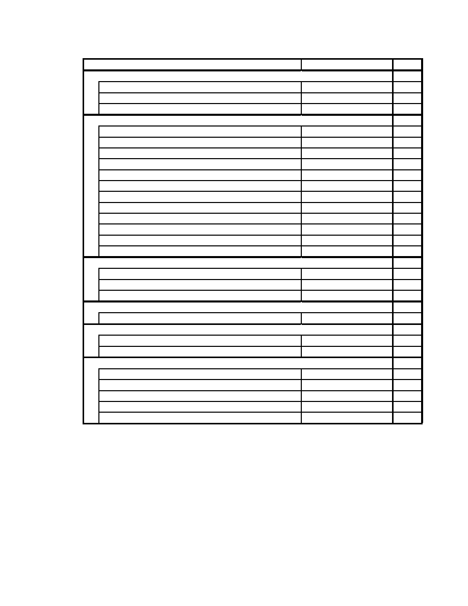
SEGA Confidential
91
User's Guide 2 Graphics Library
2.2 List of Functions
Function
Function Name
Number
<Triangle Functions>
sin function
MTH_Sin
1
cos function
MTH_Cos
2
atan function
MTH_Atan
3
<Matrix Calculation>
Initialize matrix stack
MTH_InitialMatrix
4
Clear current matrix
MTH_ClearMatrix
5
Push matrix
MTH_PushMatrix
6
Pop matrix
MTH_PopMatrix
7
Combine matrix and move horizontally
MTH_MoveMatrix
8
Combine matrix and rotate X
MTH_RotateMatrixX
9
Combine matrix and rotate Y
MTH_RotateMatrixY
10
Combine matrix and rotate Z
MTH_RotateMatrixZ
11
Combine matrix and reverse Z
MTH_ReverseZ
12
Matrix calculation and multiplication
MTH_MulMatrix
13
Matrix calculation and vertex coordinate conversion
MTH_CordTrans
14
Matrix calculation, line toggle coordinate conversion
MTH_NormalTrans
15
<3D Polygon Data Coordinate Conversion through the DSP>
Initialize Coordinate Conversion Process
MTH_PolyDataTransInit
16
Execute the Coordinate Conversion Process
MTH_PolyDataTansExec
17
Check the Coordinate Conversion Process
MTH_PolyDataTransCheck
18
<Perspective Conversion>
3D perspective conversion
MTH_Pers2D
19
<Random Number Generator>
Initialize the Random Number Generator
MTH_InitialRand
20
Get Random Number
MTH_GetRand
21
<Spline Curve Calculation>
Curve calculation, work area definition macro
MTH_INIT_CURVE
22
Curve calculation, 2D
MTH_Curve2
23
Curve calculation, 2D with tangent
MTH_Curve2t
24
Curve calculation, 3D
MTH_Curve3
25
Curve calculation, 3D with tangent
MTH_Curve3t
26
|

SEGA Confidential
92
Function
Function Name
Number
<Fixed Point Calculations>
Multiplication Routine
MTH_Mul
27
Division routine
MTH_Div
28
Fixed to floating point conversion macro
MTH_FLOAT
29
Floating to fixed point conversion macro
MTH_FIXED
30
Integer to fixed conversion routine
MTH_IntToFixed
31
Fixed to integer conversion routine
MTH_FixedToInt
32
3 item sum of product calculation
MTH_Product
33
<Other Functions>
Square Root
MTH_Sqrt
34
Hypotenuse calculation of a right angle triangle
MTH_Hypot
35
Surface normal vector calculation
MTH_CompateNormVect
36
|

SEGA Confidential
93
User's Guide 2 Graphics Library
2.3
Function Specifications
<Triangle Functions>
Title
Function
Function Name
No
Function Specification
sin function
MTH_Sin
1
Format
Fixed32 val = MTH_Sin(Fixed32 degree)
Input
degree
: Angles from -180.0 to 180.0
Output
None
Function Value
val
: sin value
Function
Returns the sin value of the indicated angle.
Title
Function
Function Name
No
Function Specification
cos function
MTH_Cos
2
Format
Fixed32 val = MTH_Cos(Fixed32 degree)
Input
degree
: Angles from -180.0 to 180.0
Output
None
Function Value
val
: cos value
Function
Returns the cos value of the indicated angle.
Title
Function
Function Name
No
Function Specification
atan function
MTH_Atan
3
Format
Fixed32 degree = MTH_Atan(Fixed32 y, Fixed32 x)
Input
y
: Height from -1.0 to 1.0
x
: Base from -1.0 to 1.0
Output
None
Function Value degree
: Angles from -180.0 to 180.0
Function
Returns the atan value from the indicated x, y values.
|

SEGA Confidential
94
<3D Matrix Calculation>
Title
Function
Function Name
No
Function Specification
Initialize matrix stack
MTH_InitialMatrix
4
Format
void MTH_InitialMatrix
( Mt hMat r i xTbl *mat r i xTbl , Ui nt 16
st ackSi ze, Mt hMat r i x *mat r i x)
Input
matrixTbl : Matrix table
stackSize : Maximum entries on a matrix stack
matrix
: Matrix stack area
Output
matrixTbl : Matrix table
Function Value
None
Function
Initializes the matrix table.
Title
Function
Function Name
No
Function Specification
Clear current matrix
MTH_ClearMatrix
5
Format
void MTH_ClearMatrix(MthMatrixTbl *matrixTbl)
Input
matrixTbl : Matrix table
Output
None
Function Value
None
Function
Clears the current matrix to a unit matrix.
Title
Function
Function Name
No
Function Specification
Push matrix
MTH_PushMatrix
6
Format
void MTH_PushMatrix(MthMatrixTbl *matrixTbl)
Input
matrixTbl : Matrix table
Output
None
Function Value
None
Function
Pushes the current matrix.
Title
Function
Function Name
No
Function Specification
Pop matrix
MTH_PopMatrix
7
Format
void MTH_PopMatrix(MthMatrixTbl *matrixTbl)
Input
matrixTbl : Matrix table
Output
None
Function Value
None
Function
Pops the current matrix.
|

SEGA Confidential
95
User's Guide 2 Graphics Library
Title
Function
Function Name
No
Function Specification
Combine matrix and move horizontally
MTH_MoveMatrix
8
Format
void MTH_MoveMatrix(MthMatrixTbl *matrixTbl,
Fixed32 x, Fixed32 y, Fixed32 z)
Input
matrixTbl : Matrix table
x
: Amount to move in X direction
y
: Amount to move in Y direction
z
: Amount to move in Z direction
Output
None
Function Value
None
Function
Combines the matrix for a horizontal move in the XYZ
direction for the current matrix.
Title
Function
Function Name
No
Function Specification
Combine matrix and rotate X
MTH_RotateMatrixX
9
Format
void MTH_RotateMatrixX
( Mt hMat r i xTbl *mat r i xTbl , Fi xed32 xDegree)
Input
matrixTbl : Matrix table
xDegree
: X axis rotation angle (Range from -180.0 to 180.0)
Output
None
Function Value
None
Function
Combines the matrix for X axis rotation for the current matrix.
Title
Function
Function Name
No
Function Specification
Combine matrix and rotate Y
MTH_RotateMatrixX
10
Format
void MTH_RotateMatrixY
( Mt hMat r i xTbl *mat r i xTbl , Fi xed32 yDegree)
Input
matrixTbl : Matrix table
yDegree
: Y axis rotation angle (Range from -180.0 to 180.0)
Output
None
Function Value
None
Function
Combines the matrix for Y axis rotation for the current matrix.
Title
Function
Function Name
No
Function Specification
Combine matrix and rotate Z
MTH_RotateMatrixZ
11
Format
void MTH_RotateMatrixZ
( Mt hMat r i xTbl *mat r i xTbl , Fi xed32 zDegree)
Input
matrixTbl : Matrix table
zDegree
: Z axis rotation angle (Range from -180.0 to 180.0)
Output
None
Function Value
None
Function
Combines the matrix for Z axis rotation for the current matrix.
|

SEGA Confidential
96
Title
Function
Function Name
No
Function Specification
Combine matrix and reverse Z
MTH_ReverseZ
12
Format
void MTH_ReverseZ(MthMatrixTbl *matrixTbl)
Input
matrixTbl : Matrix table
Output
None
Function Value
None
Function
Combines the current matrix for Z axis reversal.
Title
Function
Function Name
No
Function Specification
Matrix calculation, multiplication
MTH_MulMatrix
13
Format
void MTH_MulMatrix(MthMatrix *a, MthMatrix *b, MthMatrix *c)
Input
a
: Multiplicand matrix
b
: Multiplier matrix
Output
c
: Multiplication results matrix
Function Value
None
Function
Multiplies matrix a and b and outputs the result to c.
Title
Function
Function Name
No
Function Specification
Matrix calculation, vertex coordinate
conversion
MTH_CordTrans
14
Format
void MTH_CoordTrans
( Mt hMat r i x *mat r i x, Mt hXyz *s rc, Mt hXyz *ans )
Input
matrix
: Conversion matrix
src
: Vertex coordinates before conversion
Output
ans
: Vertex coordinates after conversion
Function Value
None
Function
Converts vertex coordinates in the conversion matrix.
Title
Function
Function Name
No
Function Specification
Matrix calculation, normal vector coordinate
conversion
MTH_NormalTrans
15
Format
void MTH_NormalTrans ( Mt hMat r i x *mat r i x, Mt hXyz *s rc, Mt hXyz
*ans )
Input
matrix
: Conversion matrix
src
: Normal vector before conversion
Output
ans
: Normal vector after conversion
Function Value
None
Function
Converts normal vector in the conversion matrix.
|

SEGA Confidential
97
User's Guide 2 Graphics Library
<3D Polygon Data Coordinate Conversion through the DSP>
Title
Function
Function Name
No
Function Specification
Initialize Coordinate Conversion Process
MTH_PolyDataTransInit
16
Format
void MTH_PolyDataTransInit(void)
Input
None
Output
None
Function Value
None
Function
Initializes the DSP and loads the coordinate conversion
program.
Title
Function
Function Name
No
Function Specification
3D Polygon Data Coordinate Conversion
MTH_PolyDataTransExec
17
Format
void MTH_PolyDataTransExec(
Mt hPol yTr ansPa rm *pol yTr ansPa rm)
Input
polyTransParm: Coordinate conversion parameter table
Output
PolyTransParm: The areas below are output from the coordinate
conversion table.
surfBright
Polygon surface brightness calc. results
transViewVertAns Vertex data after view conversion
vertBright
Vertex point brightness calc. results
transWorldVertAns Vertex data after World conversion
Function Value
None
Function
The DSP runs the following continuous process of an example
of polygon data (3D object) used by the 3D sprite display
library.
· Polygon Surface Hide Determine and Brightness Calculation
Related Parameters
<Input>
surfCount Polygon surfaces
surfPoint
Point on polygon for bright calculation
surfNormal Polygon surface normal
matrix
Conversion matrix to view coordinates
light Vector Light source vector in the view coord. system
<Output>
surfBright
Polygon surface brightness calc. results
6
31
=1:
Hide surface
=0:
Show surface
b
4
-b
0
=0x00: Darkest
0x1f =0x1f:
Lightest
· Conversion to the Vertex Coordinate System
Related Parameters
<Input> transViewVertCount
View conversion vertex entries
transViewVertSrc
Vertex data before view conversion
viewMatrix
Conversion matrix to the view coord. system
<Output> transViewVertAns
Vertex data after view conversion
|

SEGA Confidential
98
· Gouraud Display Vertex Brightness Calculation
Related Parameters
<Input>
gourVertCount Vertex point brightness vertex entries
If = 0, then brightness not calculated
vertNormal
Vertex point brightness calc. normal table
matrix
Conversion matrix to view coordinates
lightVector
Light source vector in the view coord. sys.
<Output> vertBright Vertex brightness calculation results table
0x00 =
Darkest
0x1f
= Lightest
· Conversion to the Vertex World Coordinate System
Related Parameters
<Input> transWorldVertCount Vertex data before World conversion
If = 0, conversion to world not
executed.
transWorldVertSrc
Vertex data table before world coord.
conversion
worldMatrix
Conversion matrix to world coordinates
<Output> transWorldVertAns
Vertex data table after conversion to
world coordinate system
Title
Function
Function Name
No
Function Specification
Check the Coordinate Conversion Process
MTH_PolyDataTansCheck
18
Format
void MTH_PolyDataTransCheck(void)
Input
None
Output
None
Function Value
None
Function
Waits until the DSP coordinate conversion process is finished.
<Perspective Conversion>
Title
Function
Function Name
No
Function Specification
3D perspective conversion
MTH_Pers2D
19
Format
void MTH_Pers2D ( Mt hXyz *p3d, Mt hXy *uni t Pi xel , XyI ni t *p2d )
Input
p3d
: View coordinate system 3D vertex coordinates
unitPixel : Screen XY unit pixels
Output
p2d
: 2D screen coordinates after perspective conversion
Function Value
None
Function
Converts from 3D to 2D perspective by setting the screen to -1.0
as the view of the coordinate system base point. The size of 1.0
on the screen corresponds to the XY unit pixels.
|

SEGA Confidential
99
User's Guide 2 Graphics Library
<Random Number Generator>
Title
Function
Function Name
No
Function Specification
Initialize the Random Number Generator
MTH_InitialRand
20
Format
void MTH_InitalRand(Uint32 initVal)
Input
initVal
: Initial parameter value of the random number generator
Output
None
Function Value
None
Function
Sets the initial parameter for calculation of the random number
returned by MTH_GetRand. Unless this routine is called, the
initial value of the random number generator will be 0.
Title
Function
Function Name
No
Function Specification
Get Random Number
MTH_GetRand
21
Format
Uint32 randVal = MTH_GetRand(void)
Input
None
Output
None
Function Value
randVal
: Generates a random number from 0x00000000 to 0xffffffff.
Function
Returns a random number each time it is run.
|

SEGA Confidential
100
<Spline Curve Calculation>
Title
Function
Function Name
No
Function Specification
Curve calculation, work area
definition macro
MTH_INIT_CURVE
22
Format
MTH_INIT_CURVEWORK(WORK_AREA, POINT_MAX)
Input
WORK_AREA : Work area name
POINT_MAX
: Maximum input points
Function
Defines as user area the area needed to execute the curve
calculation function. This definition area pointer is returned to
each curve calculation function as a parameter.
The area reserved is the maximum input points x 36bytes.
The count of the output coordinate is (in_n - 1) *step+ 1, so
prepare an aray larger than that size.
Title
Function
Function Name
No
Function Specification
2D
MTH_Curve2
23
Format
Ui nt 32 count = MTH_Cur ve2( Mt hCur veW
o rk *wo rk, Mt hXy *i n_a ray,
Ui nt 32 i n_n, Ui nt 32 out _n, MthXy *out _a ray)
Input
work
: Work area pointer
in_aray
: Input coordinate aray
in_n
: Input coordinate count
out_n
: Output coordinate count
Output
out_aray : Output coordinate aray
Function Value
count
: More than 2 output coordinates
0: parameter error
Function
work indicates the work area reserved by the
MTH_INIT_CURVE macro.
-
in_aray indicates the pointer to input coordinates that pass
through the curve.
-
in_n indicates the number in in_aray. Please indicate more
than 3.
-
out_n indicates the number in out_aray. Please indicate more
than 2.
-
out_aray indicates the pointer that receives the calculation
results. It returns the aray of the output coordinates that pass
through the curve.
|

SEGA Confidential
101
User's Guide 2 Graphics Library
Title
Function
Function Name
No
Function Specification
Curve calculation, 2D with connectors
MTH_Curve2t
24
Format
Uni t 32 count = MTH_Cur ve2( Mt hCur veW
o rk *wo rk, Mt hXy *i n_a ray,
Uni t 32 i n_n, Uni t 32 out _n, MthXy *out _a ray Mt hXy *t an_a ray)
Input
work
: Work area pointer
in_aray
: Input coordinate aray
in_n
: Input coordinate count
out_n
: Output coordinate count
Output
out_aray : Output coordinate aray
tan_aray
: Connector line toggle of each output coordinates
Function Value
count
: More than 2 output coordinates
0: parameter error
Function
work indicates the work area reserved by the
MTH_INIT_CURVE macro.
-
in_aray indicates the pointer to input coordinates that pass
through the curve.
-
in_n indicates the number in in_aray. Indicate more than 3.
-
bout_n indicates the number in out_aray. Indicate more than
2.
-
out_aray indicates the pointer that receives the calculation
results. It returns the aray of the output coordinates that pass
through the curve.
-
tan_aray returns the tangent vector toggle that shows the
direction of progress for each output coordinate. The size of
the tangent vector is 1.0.
Title
Function
Function Name
No
Function Specification
3D
MTH_Curve3
25
Format
Ui nt 32 count = MTH_Cur ve3( Mt hCur veW
o rk *wo rk, Mt hXyz *i n_a ray,
Uni t 32 i n_n, Uni t 32 out _n, MthXyz *out _a ray)
Input
work
: Work area pointer
in_aray
: Input coordinate aray
in_n
: Input coordinate count
out_n
: Output coordinate count
Output
out_aray : Output coordinate aray
Function Value
count
: More than 2 output coordinates
0: parameter error
Function
work indicates the work area reserved by the
MTH_INIT_CURVE macro.
-
in_aray indicates the pointer to input coordinates that pass
through the curve.
-
in_n indicates the number in in_aray. Indicate more than 3.
-
out_n indicates the number in out_aray. Indicate more than 2.
-
out_aray indicates the pointer that receives the calculation
results. It returns the aray of the output coordinates that pass
through the curve.
|

SEGA Confidential
102
Title
Function
Function Name
No
Function Specification
Curve calculation, 3D with tangent
MTH_Cruve3t
26
Format
Ui nt 32 count = MTH_Cur ve3t ( Mt hCur veW
o rk *wo rk, Mt hXyz *i n_a ray,
Uni t 32 i n_n, Uni t 32 out _n, MthXyz *out _a ray, Mt hXyz *t an_a ray)
Input
work
: Work area pointer
in_aray
: Input coordinate aray
in_n
: Input coordinate count
out_n
: Output coordinate count
Output
out_aray : Output coordinate aray
tan_aray
: Tangent vector toggle of each output coordinates
Function Value
count
: More than 2 output coordinates
0: parameter error
Function
work indicates the work area reserved by the
MTH_INIT_CURVE macro.
- in_aray indicates the pointer to input coordinates that pass
through the curve.
- in_n indicates the number in in_aray. Indicate more than 3.
- out_n indicates the number in out_aray. Indicate more than 2.
- out_aray indicates the pointer that receives the calculation
results. It returns the aray of the output coordinates that pass
through the curve.
- tan_aray returns the tangent vector toggle that shows the
direction of progress for each output coordinate. The size of
tangent vector is 1.0.
Cautions on Use
These curve calculation functions were developed with process
speed as a top priority, so there is no overflow check. But, if a
large number is encountered during function calculation, an
overflow will occur. The allowable range of input data is as
follows:
· Distance between points: more than 0.1.
· Point coordinate value range: between -1000 and 1000.
Also, because of possible algorithm changes in future versions,
the same output coordinates may not be produced with the
same parameters.
|

SEGA Confidential
103
User's Guide 2 Graphics Library
<Fixed Point Calculations>
Title
Function
Function Name
No
Function Specification
Multiplication Routine
MTH_Mul
27
Format
Fixed32 result = MTH_Mul(Fixed32 a, Fixed32 b)
Input
a
: Multiplicand
b
: Multiplier
Output
None
Function Value
result
: Multiplication results
Function
Does fixed point multiplication.
Title
Function
Function Name
No
Function Specification
Division routine
MTH_Div
28
Format
Fixed32 result = MTH_Div(Fixed32 a, Fixed32 b)
Input
a
: Dividend
b
: Divisor
Output
None
Function Value
result
: Division results
Function
Does fixed point division.
Title
Function
Function Name
No
Function Specification
Fixed to floating point conversion macro
MTH_FLOAT
29
Format
Float b = MTH_FLOAT(Fixed32 a)
Input
a
: Fixed point data
Output
None
Function Value
b
: Conversion results to floating point format.
Function
Macro to convert fixed point data to floating point data.
Title
Function
Function Name
No
Function Specification
Floating to fixed point conversion macro
MTH_FIXED
30
Format
Fixed32 b = MTH_FIXED(Float a)
Input
a
: Floating point data
Output
None
Function Value
b
: Conversion results to fixed point format.
Function
Macro to convert floating point data to fixed point data.
|

SEGA Confidential
Title
Function
Function Name
No
Function Specification
Integer to fixed conversion routine
MTH_IntToFixed
31
Format
Fixed32 b = MTH_IntToFixed(Sint32 a);
Input
a
: Integer data
Output
None
Function Value
b
: Conversion results to fixed point data.
Function
Macro to convert integer data to fixed point data.
Title
Function
Function Name
No
Function Specification
Fixed to integer conversion routine
MTH_FixedToInt
32
Format
Sint32 b = MTH_FixedToInt(Fixed a)
Input
a
: Fixed point data
Output
None
Function Value
b
: Conversion results to integer data format.
Function
Macro to convert fixed point data to integer data.
Title
Function
Function Name
No
Function Specification
3 item sum of product calculation
MTH_Product
33
Format
Fixed32 result = MTH_Product(Fixed32 *a, Fixed32 *b)
Input
a
: 3 Multiplicand data lines
b
: 3 multiplier data lines
Output
None
Function Value
results
: Product sum of the multiplication results
Function
Does calculation processing as follows:
result = a[0]*b[0] + a[1]*b[1] + a[2]*b[2]
104
|

SEGA Confidential
105
<Other Functions>
Title
Function
Function Name
No
Function Specification
Square Root
MTH_Sqrt
34
Format
Fixed32 result = MTH_Sqrt(Fixed32x)
Input
x
: Correct fixed point real number value
Output
None
Function Value
result
: Calculated square root value
Function
Calculates and returns the square root of the input value.
Title
Function
Function Name
No
Function Specification
Hypotenuse calculation of a right
angle triangle
MTH_Hypot
35
Format
Fixed32 z = MTH_Hypot(Fixed32 x, Fixed32 y)
Input
x
: Right angle triangle base length
y
: Right angle triangle perpendicular length
Output
None
Function Value
z
: Hypotenuse length of the right angle triangle
Function
Returns z that fulfills the following equation.
z
2
=x
2
+y
2
but z
0
Title
Function
Function Name
No
Function Specification
Surface normal vector calculation
MTH_ComputeNormVect
36
Format
void MTH_ComputeNormVect (Fixed32 surfNormK,
MthXyz *p0, MthXyz *p1, MthXyz *p3, MthXyz *normal)
Input
surfNormK :
Vertex distance correction value
p0
: Coordinate of first vertex right of top of screen.
p1
: Coordinate of second vertex right of top of screen.
p2
: Coordinate of third vertex to right of top of screen.
Output
Normal
: Normal screen vecter (uint vecter)
Function Value
None
Function
Calculates normally for the indicated right hand vertex on the
screen. The direction in relation to the normal vector is the
opposite of right twist. The normal vertor calculation is based
on the difference between 2 of 3 vertexes on the screen and
finding the relationship.
The correction value of the indicated vertex interval is
converted to absolute values to find the maternal relationship
based on the 2 vectors. This is because if the 3 pointers on the
screen are too small or too large, the 32 bit fixed decimal
calculation either underflows or overflows, making a correct
calculation difficult. To avoid this, the correction value is used
to make sure the absolute value is around 1.0 when the
difference of the 23 screen points vector is found. If the vertex
interval correction flag is negative, the normal vector will be in
the opposite direction.
User's Guide 2 Graphics Library
|

SEGA Confidential
(There is no page 106 in the original Japanese document.)
106
|

SEGA Confidential
DSP I/F Library
1.0 Guide
1.1 Objective
The purpose of this library is to provide an interface for DSP program control.
1.2 Overview
This library has the following interfaces prepared.
· Program load
· Data write
· Data read
· Start program execution
· Stop program execution
· Check for execution end
An overview of each function is provided below.
1.3 Function Overview
· Program load
Transfers the DSP program stored in work RAM, etc., to DSP program RAM.
· Data write
Transfers the DSP program data (parameters) stored in work RAM, etc., to DSP
data RAM.
· Data read
Reads DSP data and RAM data (results, etc.)
· Start program execution
Sets the program counter and starts the DSP program execution.
· Stop program execution
Stops execution of the DSP program.
· Check for execution end
Checks to see if the DSP program has stopped executing.
107
User's Guide 2 Graphics Library
|

SEGA Confidential
1.4 Calling Sequence
The calling sequence from program load until results appearing is shown below.
void GoDsp ()
{
Uint32 dsp_result[10]; /* DSP result storage variable */
DSP_WriteData(DSP_RAM_1 | 0, (Uint32 *)0x6050000, 15);
/* Transfer 15 times of data to DSP data RAM, RAM1 from work RAM
*/
DSP_LoadProgram(0, (Uint32 *)0x6050100, 256);
/* Transfer 256 times of data to DSP program RAM from work RAM
*/
DSP_Start(0);
/* Execute DSP program from 0x00
*/
while(DSP_CheckEnd(&dsp_status) == DSP_NOT_END); /* Loop
until ends */
DSP_ReadData(dsp_result, DSP_RAM_2 | 0, 10);
/*
Transfer 10 times of data from DSP data RAM, RAM2 to DSP result storage variable */
......
}
108
|

SEGA Confidential
2.0 Reference
2.1 List of Functions
Function
Function Name
Number
Program load
DSP_LoadProgram
1
Data write
DSP_WriteData
2
Data read
DSP_ReadData
3
Start program execution
DSP_Start
4
Stop program execution
DSP_Stop
5
Check for execution end
DSP_CheckEnd
6
2.2 Function Specifications
Title
Function
Function Name
No
Function Specification
Program load
DSP_LoadProgram
1
Format
void DSP_LoadProgram(Uint8 dst, Uint32 *src, Uint16 count)
Input
dst
: DSP program RAM address
src
: DSP program storage lead address
count
: Transfer repetitions (long word units)
Output
None
Function Value
None
Function
Transfers from the indicated DSP program storage lead address
data equal to the number of repetitions specified (long word
units) to the DSP program RAM address.
Title
Function
Function Name
No
Function Specification
Data write
DSP_WriteData
2
Format
void DSP_WriteData(Uint8 dst, Uint32 *src, Uint16 count)
Input
dst
: DSP data RAM address
src
: DSP data storage lead address
count
: Transfer repetitions (long word units)
Output
None
Function Value
None
Function
Transfers from the indicated DSP data storage address data
equal to the number of repetitions specified (long word units)
to the address in the DSP data RAM. Designates the DSP data
RAM address, including the selector flag in 8bit.
DSP_RAM_0
DSP_RAM_1
DSP_RAM_2
DSP_RAM_3
DSP_RAM_2 |3 = Relative third long word RAM2 page.
109
User's Guide 2 Graphics Library
|

SEGA Confidential
Title
Function
Function Name
No
Function Specification
Data read
DSP_ReadData
3
Format
void DSP_ReadData(Uint32 *dst, Uint8 src, Uint16 count)
Input
dst
: DSP data storage lead address
src
: DSP data RAM address
count
: Transfer repetitions (long word units)
Output
None
Function Value
None
Function
Transfers from the indicated DSP data RAM, data equal to the
number of repetitions specified (long word units) to the DSP
data storage address. Designates the DSP data RAM address,
including the selector flag in 8bit.
Title
Function
Function Name
No
Function Specification
Start program execution
DSP_Start
4
Format
void DSP_Start(Uint8 pc)
Input
pc
: Program counter
Output
None
Function Value
None
Function
Executes the DSP program from the indicated program
counter.
Title
Function
Function Name
No
Function Specification
Stop program execution
DSP_Stop
5
Format
void DSP_Stop(void)
Input
None
Output
None
Function Value
None
Function
Stops the DSP program currently running.
110
|

SEGA Confidential
Title
Function
Function Name
No
Function Specification
Check for execution end
DSP_CheckEnd
6
Format
Uint8 DSP_CheckEnd(void)
Input
None
Output
None
Function Value
End flag
Constant Name
Constant Name
Explanation
DSP_END
Finished executing
DSP_NOT_END
Executing
Function
Checks to see if the DSP program has finished running or not.
111
User's Guide 2 Graphics Library
|

SEGA Confidential
INDEX
D
DSP_CheckEnd ........................... 111
DSP_LoadProgram ..................... 109
DSP_ReadData ............................ 110
DSP_Start ..................................... 110
DSP_Stop...................................... 110
SDP_WriteData ........................... 109
M
MTH_Atan ................................... 93
MTH_ClearMatrix ...................... 94
MTH_ComputeNormVect ......... 105
MTH_CordTrans ......................... 96
MTH_Cos ..................................... 93
MTH_Curve2............................... 100
MTH_Curve2............................... 101
MTH_Curve3............................... 101
MTH_Curve3t ............................. 102
MTH_Div ..................................... 103
MTH_FIXED ................................ 103
MTH_FixedToInt......................... 104
MTH_FLOAT............................... 103
MTH_GetRand ............................ 109
MTH_Hypot ................................ 105
MTH_INIT-CURVE .................... 100
MTH_Initial Matrix .................... 94
MTH_InitialRand ........................ 99
MTH_IntToFixed......................... 104
MTH_MoveMatrix...................... 95
MTH_Mul .................................... 103
MTH_MulMatrix ........................ 96
MTH_NormalTrans .................... 96
MTH_Pers2d................................ 98
MTH_PolyDataTransCheck ...... 98
MTH_PolyDateTransExec ......... 97
MTH_PolyDataTransInit ........... 97
MTH_PopMatrix ......................... 94
MTH_Product.............................. 104
MTH_PushMatrix ....................... 94
MTH_ReverseZ ........................... 96
MTH_RotateMatrixX .................. 95
MTH_RotateMatrixY .................. 95
MTH_RotateMatrixZ .................. 95
MTH_Sin ...................................... 93
MTH_Sqrt .................................... 105
MthMatrix .................................... 89
MthMatrixTbl .............................. 89
MthPolyTransParm..................... 90
MthViewLight ............................. 90
MthXy ........................................... 89
MthXyz ......................................... 89
S
SCL_AbortAutoVE ..................... 86
SCL_AllocColRam ...................... 79
SCL_Close .................................... 69
SCL_DisableBlur ......................... 84
SCL_DisableLineCol................... 84
SCL_DisplayFrame ..................... 85
SCL_EnableBlur .......................... 84
SCL_EnableLineCol .................... 84
SCL_FreeColRam ........................ 79
SCL_GetColRamMode ............... 78
SCL_GetColRamOffset .............. 80
SCL_GetPriority .......................... 81
SCL_IncColOffset........................ 83
SCL_InitConfigTb ....................... 66
SCL_InitLineParamTb ................ 69
SCL_InitLineParmTb .................. 69
SCL_InitRotateTable ................... 71
SCL_InitVramConfigTb ............. 66
SCL_Move .................................... 70
SCL_MoveTo ............................... 70
SCL_Open .................................... 69
SCL_Rotate .................................. 73
SCL_RotateTo .............................. 73
SCL_Scale ..................................... 71
SCL_SetAutoColChg .................. 80
SCL_SetAutoColMix .................. 82
SCL_SetAutoColOffset............... 83
SCL_SetBack ................................ 75
112
|

SEGA Confidential
SCL_SetCoefficientData ............. 74
SCL_SetColMixMode ................. 81
SCL_SetColMixRate ................... 81
SCL_SetColOffset........................ 82
SCL_SetColRam .......................... 79
SCL_SetColRamMode ................ 78
SCL_SetConfig ............................ 67
SCL_SetCycleTable ..................... 67
SCL_SetDisplayMode ................ 65
SCL_SetFrameInterval ............... 85
SCL_SetLineParam ..................... 70
SCL_SetLineWindow ................. 77
SCL_SetLncl ................................. 75
SCL_SetMosaic ............................ 74
SCL_SetPriority ........................... 80
SCL_SetRotateCenter ................. 72
SCL_SetRotateCenterDisp ......... 72
SCL_ SetRotateViewPoint.......... 72
SCL_SetShadowBit ..................... 85
SCL_SetSpriteMode .................... 78
SCL_SetSpriteWindow ............... 77
SCL_SetVramconfig .................... 66
SCL_SetWindow ......................... 76
SCL_VblankEnd .......................... 86
SCL_VblankStart ......................... 86
SCL_Vdp2Init .............................. 65
Sclconfig ....................................... 57
SclDataset ..................................... 60
SclDisplayX, SclDisplayY .......... 62
ScILineParam............................... 59
SclLineTb ...................................... 55
SclLineWindowTb ...................... 55
SclNorscl ...................................... 61
SclRgb ........................................... 56
SclRgb ........................................... 56
SclRotscl ....................................... 61
SclSclconfig .................................. 57
SclSysreg ...................................... 60
SclVramConfig ............................ 56
SclWinscl ...................................... 62
SclXy ............................................. 55
SclXyz ........................................... 55
SPR_2AllocBlock ......................... 31
SPR_2CharNo .............................. 25
SPR_2CharNoToVram ................ 25
SPR_2CloseCommand ............... 26
SPR_2ClrAllChar ........................ 25
SPR_2ClrChar .............................. 24
SPR_2Cmd ................................... 30
SPR_2DEFINE_WORK .............. 22
SPR_2DefineWork ....................... 22
SPR_2DistSpr ............................... 30
SPR_2FlushDrawPrty ................. 30
SPR_2FrameChgIntr ................... 23
SPR_2FrameEraseData ............... 23
SPR_2FreeBlock ........................... 31
SPR_2GourTblNo ....................... 25
SPR_2GourTblNooV ram ......... 25
SPR_2Initial.................................. 22
SPR_2Line .................................... 27
SPR_2LocalCoord ....................... 26
SPR_2LookupTblNo ................... 25
SPR_LookupTblNoToVram ....... 25
SPR_2NormSpr ........................... 29
SPR_2OpenCommand ............... 26
SPR_2PolyGon ............................ 28
SPR_2Polygon ............................. 28
SPR_2PolyLine ............................ 28
SPR_2ScaleSpr ............................. 29
SPR_2SetChar .............................. 24
SPR_2SetGourTbl........................ 23
SPR_2SetLookupTbl ................... 24
SPR_2SetTvMode ........................ 22
SPR_2Sysclip ............................... 27
SPR_2UserClip ............................ 27
SPR_2UsrClip .............................. 27
SPR_3CallAllCluster .................. 41
SPR_3ChangeTexColor .............. 42
SPR_3ClrTexture ......................... 41
SPR_3DEFINE_WORK .............. 37
SPR_3DefineWork ....................... 37
SPR_3DrawModel ...................... 40
SPR_3Flush .................................. 41
SPR_3GetStatus ........................... 43
SPR_3Initial.................................. 38
SPR_3MoveCluster ..................... 40
SPR_3SetClipLevel ..................... 38
SPR_3SetDrawSpeed .................. 43
SPR_3SetLight ............................. 39
SPR_3SetPixelCount ................... 38
113
User's Guide 2 Graphics Library
|

SEGA Confidential
SPR_3SetSurfNormVect ............. 43
SPR_3SetTexture ......................... 41
SPR_3SetView.............................. 39
SPR_3SeyZSortMinMax ............. 42
SPR_GetStatus ............................. 17
SPR_Initial.................................... 16
SPR_READ_REG ........................ 18
SPR_SetEosMode ........................ 18
SPR_SetEraseData ....................... 17
SPR_SetTvMode .......................... 16
SPR_WaitDrawEnd ................. 17, 18
SPR_WRITE_REG ....................... 18
Spr3dStatus ................................. 36
SprCluster .................................... 32
SprGourTbl .................................. 19
SprInbetInf ................................... 36
SprLookupTbl ............................. 19
SprObject3D ................................. 34
SprSpCmd .................................... 20
SprSpStatus .................................. 15
SprSurface .................................... 35
SprTexture .................................... 36
SprVaddr ...................................... 19
X
XyInt ............................................. 19
114
|