
SEGA Confidential
General Notice
When using this document, keep the following in mind:
1. This document is confidential. By accepting this document you acknowledge that you are bound
by the terms set forth in the non-disclosure and confidentiality agreement signed separately and /in
the possession of SEGA. If you have not signed such a non-disclosure agreement, please contact
SEGA immediately and return this document to SEGA.
2. This document may include technical inaccuracies or typographical errors. Changes are periodi-
cally made to the information herein; these changes will be incorporated in new versions of the
document. SEGA may make improvements and/or changes in the product(s) and/or the
program(s) described in this document at any time.
3. No one is permitted to reproduce or duplicate, in any form, the whole or part of this document
without SEGA'S written permission. Request for copies of this document and for technical
information about SEGA products must be made to your authorized SEGA Technical Services
representative.
4. No license is granted by implication or otherwise under any patents, copyrights, trademarks, or
other intellectual property rights of SEGA Enterprises, Ltd., SEGA of America, Inc., or any third
party.
5. Software, circuitry, and other examples described herein are meant merely to indicate the character-
istics and performance of SEGA's products. SEGA assumes no responsibility for any intellectual
property claims or other problems that may result from applications based on the examples
describe herein.
6. It is possible that this document may contain reference to, or information about, SEGA products
(development hardware/software) or services that are not provided in countries other than Japan.
Such references/information must not be construed to mean that SEGA intends to provide such
SEGA products or services in countries other than Japan. Any reference of a SEGA licensed prod-
uct/program in this document is not intended to state or simply that you can use only SEGA's
licensed products/programs. Any functionally equivalent hardware/software can be used instead.
7. SEGA will not be held responsible for any damage to the user that may result from accidents or any
other reasons during operation of the user's equipment, or programs according to this document.
(6/27/95- 002)
NOTE: A reader's comment/correction form is provided with this
document. Please address comments to :
SEGA of America, Inc., Developer Technical Support (att. Evelyn Merritt)
150 Shoreline Drive, Redwood City, CA 94065
SEGA may use or distribute whatever information you supply in any way
it believes appropriate without incurring any obligation to you.
|

SEGA Confidential
TM
Saturn Overview
Manual
(temporary version 1)
June 6, 1994
Doc. #ST-103-R1-040194
© 1994 SEGA. All Rights Reserved.
CONTENTS
Introduction
(i)
Manual Layout
(i)
Related Manuals
(ii)
Definitions
(iii)
List of Figures
(vi)
List of Tables
(vii)
Chapter 1 Introduction to Saturn
1
1.1 Highlights
2
Chapter 2 Structure
5
2.1 Hardware Specifications
6
2.2 System Configuration
7
2.3 Description of Each Part
8
Chapter 3 Functions
11
3.1 CPU
12
3.2 SCU
13
3.3 VDP1
16
3.4 VDP2
27
3.5 SCSP
38
3.6 CD-ROM
42
3.7 Other Items
51
Index
53
|

SEGA Confidential
READER CORRECTION/COMMENT SHEET
Chpt.
pg. #
Correction
Corrections:
General Information:
Your Name
Phone
Document number
Date
Document name
Questions/comments:
Keep us updated!
If you should come across any incorrect or outdated information while reading through the attached
document, or come up with any questions or comments, please let us know so that we can make the
required changes in subsequent revisions. Simply fill out all information below and return this form to
the Developer Technical Support Manager at the address below. Please make more copies of this form if
more space is needed. Thank you.
Fax:
(415) 802-3963
Attn: Manager,
Developer Technical Support
Mail:
SEGA OF AMERICA
Attn: Manager,
Developer Technical Support
275 Shoreline Dr. Ste 500
Redwood City, CA 94065
Where to send your corrections:
ST-103-R1-040194
Saturn Overview Manual
|

SEGA Confidential
REFERENCES
In translating/creating this document, certain technical words and/or phrases were interpreted with the
assistance of the technical literature listed below.
1.
KenKyusha New Japanese-English Dictionary
1974 Edition
2.
Nelson's Japanese-English Character Dictionary
2nd revised version
3.
Microsoft Computer Dictionary
4.
Japanese-English Computer Terms Dictionary
Nichigai Associates
4th version
|

SEGA Confidential
Introduction
This manual gives an overview of the hardware for Saturn, Sega's Multimedia
Home Entertainment Device, which contains a 32-bit RISC (Reduced Instruction Set
Computer) processor. This manual explains the features and functions of Saturn to
those who develop game software.
Manual Layout
This manual consists of the following chapters, supplements, and index.
Chapter 1
Introduction to Saturn
The features of Saturn are explained.
Chapter 2
Structure
The internal structure of Saturn plus hardware specifications
are explained.
Chapter 3
Functions
The main functions of Saturn are explained.
· CPU
The main CPU, sound CPU, I/O controller.
· SCU
Control of each bus (A-bus, B-bus, CPU-bus),
DMA transfer, and matrix calculation (DSP).
· VDP1
Control of drawing and defines draw control.
· VDP2
Control of the scroll screen and display.
· SCSP
Sound control of the PCM/FM sound source.
· CD-ROM
An overview of the CD-ROM and MPEG.
· Miscellaneous
Explains the SMPC.
i
|

SEGA Confidential
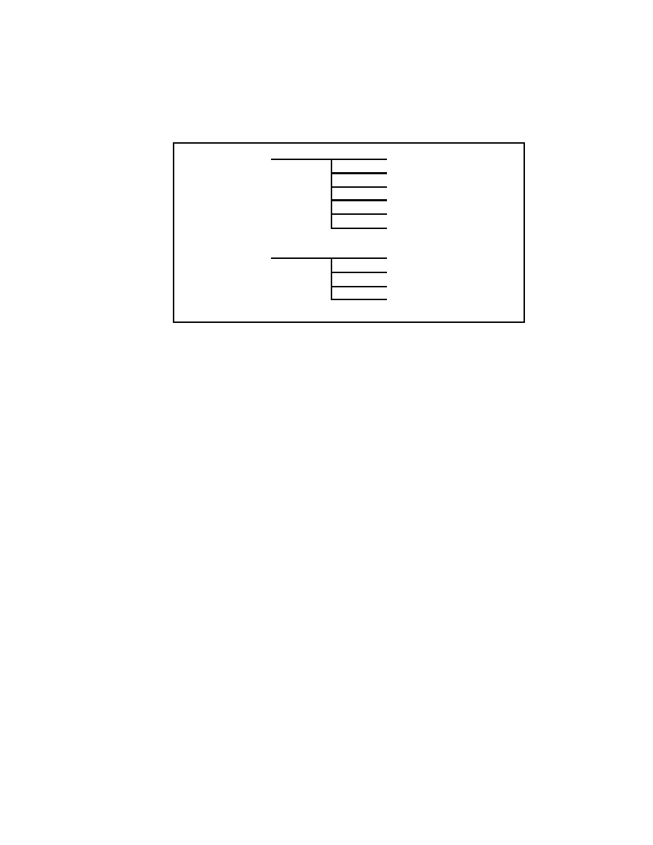
VDP1
User's
Manual
VDP2
User's
Manual
SCU
User's
Manual
SCSP
User's
Manual
SATURN
OVERVIEW
SMPC
User's
Manual
Related Manuals
ii
|

SEGA Confidential
Definitions
DSP (Digital Signal Processor)
This high-speed digital processor mainly performs rapid addition and subtraction.
Gouraud Shading
Gouraud is one type of computer algorithm.
This process computes the color of each position (dot, pixel) of each object being
displayed. Places hit by light are bright, and places shadowed are dark.
C3
An error process that corrects errors when data is read from a CD.
Frame Buffer
Frame buffer is RAM that stores pictures to be displayed. The line buffer was lim-
ited to pictures arranged in a horizontal direction, but with the RAM of the TV
screen size, there you are no longer limits in the horizontal direction.
Pixel
A unit that represents a picture element in a drawing.
PCM Sound Generator (Pulse Code Modulation Sound Generator)
A method of storing in memory PCM data created from sound, reading the sound
from memory at the time that the sound is to be played, and outputting the sound.
Interlace
An image output scan system that obtains the screen image of a single frame by
scanning it twice.
iii
|

SEGA Confidential
MPEG (Motion Picture (image coding) Expert Group)
An international standard of compression for color motion images (including voice)
of television and video. This standard allows the playing of Full Screen, Full Color,
Full Motion, and CD Quality Audio. Besides conforming to the international stan-
dard, it also has original special functions.
Parts
Divides textured and non-textured parts in a drawing done by the draw command.
Perspective
A technique for creating the impression of distance in computer graphics by show-
ing distance objects as small and nearby objects as large.
Sprite
Image patterns that can be rapidly moved and re-drawn. By preparing a number of
sprite patterns and re-drawing them while moving designated coordinates, an
animation effect can be produced in which the game character appears to be mov-
ing.
High Resolution
Both the normal TV and special monitor are able to display at a high resolution, but
the special monitor has a higher resolution.
Texture Mapping
A computer graphics technique that allows a pattern to be placed on an object.
PCM (Pulse Code Modulation)
A method of dividing sound (wave forms) according to a time axis, and converting
the peak values into digital data. Data found by this method is called PCM data.
iv
|

SEGA Confidential
Effect Data
Expresses the resulting sound obtained when a sound created by the sound genera-
tor is affected by passing through the DSP.
Reverb
As one type of sound field effect, one can produce the atmosphere of a hall, stage
room, steel plate, etc.
PLL (Phase Locked Loop)
Refers to the phase-locked circuit (IC) that follows to the input signal.
IPL (Initial Program Loading)
A list process language. It outputs the designation that loads programs from the
designated I/O device to the processing device.
Clipping
Clipping removes all image data located outside of the designated draw access area.
PAL System (Phase Alternation by Line system)
Developed in West Germany, this is a color television broadcasting standard of 625
scan lines and 25 images per second.
NTSC System (National Television System Committee system)
Recognized by the FCC (Federal Communication Commission) and applied by
Japan, the United States, South Korea,among others; this standard of color television
broadcasting has 525 scan lines and 30 images per second.
v
|

SEGA Confidential
List of Figures
Chapter 2 Structure
Figure 2.1 System Block Diagram
7
Chapter 3 Functions
Figure 3.1 SCU System Configuration
13
Figure 3.2 VDP1 System Configuration
16
Figure 3.3 Regular Sprites
19
Figure 3.4 Scaled Sprites
19
Figure 3.5 Distorted Sprites
20
Figure 3.6 Polygon, Polyline, Line
21
Figure 3.7 Configuration of the Color Bank Method
22
Figure 3.8 Gouraud Shading
24
Figure 3.9 Mesh Process
24
Figure 3.10 System Clipping
25
Figure 3.11 User Clipping
25
Figure 3.12 VDP2 System Configuration
27
Figure 3.13 Scroll, Priority Functions
29
Figure 3.14 Mosaic Pattern
31
Figure 3.15 Image Modification by Axis Rotation
31
Figure 3.16 Image Modification by Screen Axis
32
Figure 3.17 Cell Format Scroll Screen
33
Figure 3.18 Bit Map Scroll Screen and Data Setting Relationship
33
Figure 3.19 Windows
34
Figure 3.20 Priority Function
34
Figure 3.21 Color Calculation Function
35
Figure 3.22 Insertion of the Line Color Screen
36
Figure 3.23 Shadow Function
36
Figure 3.24 Blur Calculation Function
37
Figure 3.25 SCSP System Configuration
38
Figure 3.26 Tunnel and BGM Reverb
40
Figure 3.27 Tennis Game Example
41
Figure 3.28 CD-ROM System Configuration
42
Figure 3.29 CD-ROM System Data Flow
44
Figure 3.30 Stream Select Function
45
Figure 3.31 Window Function
46
Figure 3.32 Interpolation, Shading, Mosaic Functions
47
Figure 3.33 Chroma Key Function
48
Figure 3.34 SMPC System Configuration
51
vi
|

SEGA Confidential
List of Tables
Chapter 2 Structure
Table 2.1 Hardware Specifications <Main System>
6
Table 2.2 Hardware Specifications <Subsystem>
6
Chapter 3 Functions
Table 3.1 CPU Specifications
12
Table 3.2 SCU System Specifications
14
Table 3.3 VDP1 System Specifications
17
Table 3.4 Parts Classification
18
Table 3.5 Interlace
21
Table 3.6 Types of Color Operations
23
Table 3.7 VDP2 System Specifications
28
Table 3.8 Scroll Screen Functions
30
Table 3.9 SCSP System Specifications
39
Table 3.10 CD-ROM System Specifications
43
Table 3.11 CD Drive Specifications
43
Table 3.12 Corresponding Standards
50
Table 3.13 SMPC Functions
52
Table 3.14 Saturn Digital PAD Specifications
52
vii
|

SEGA Confidential
Chapter 1 Introduction to Saturn
Contents
Highlights
2
Saturn Overview Manual
1
|

SEGA Confidential
2
1.1
Highlights
· Leading Edge CD-ROM Drive
· High-Speed Micro-Processor
· Large-Capacity Memory
· The main CPU is a 32-bit RISC chip
- SH-2 loader that supports a DSP-type computer.
· Memory
- 32 Mbits (4 Mbytes)
- 4 Mbit (512 Kbyte) CD-ROM
· Powerful Graphics Functions
- Up to 16,777,216 colors
- 24 million pixels/Sec (VDP1)
- Sprite processor that can display polygons
- High performance background processor
|

SEGA Confidential
SATURN
SEGA
DUAL CPU MULTI AMUSEMENT PLAYER
SEGA CD ROM / CARTRIDGE
· Improved Sound Functions
- 32 Channel PCM sound generator
- FM sound generator
- Audio-only effect DSP loader
· Leading Edge CD-ROM Drive
- 32-bit RISC chip SH-1 loader
- MPEG (optional)
· Development Language
- C language, Assembly language
Saturn Overview Manual
3
|

SEGA Confidential
4
|

SEGA Confidential
Chapter 2 Structure
Contents
2.1 Hardware Specifications
6
2.2 System Configuration
7
2.3 Description of each Part
8
Saturn Overview Manual
5
|

SEGA Confidential
2.1
Hardware Specifications
Saturn hardware specifications are shown below.
Table 2.1 Hardware Specifications <Main System>
Table 2.2 Hardware Specifications <Subsystem>
6
SH-2 X 2
CPU
32-bit RISC Chip 28.6MHz / 26.8
Internal Math Processor
RAM
2MB
CPU BLOCK
ROM
512KB
SCU
DMA 2 ch
DSP 14.3 MHz
SMPC
RTC 1 MHz (accuracy)
Employs Peripheral Interface
VDP1
Max. 400,000 pixels, 1/60 sec. transfer
VIDEO BLOCK
VDP2
Screen Resolution 320 dot (H) X 224 dot (V)
up to 5 background screens
RAM
VDP1: 1 MB
VDP2: 512 KB
SCSP
PCM 32 ch, max. 44.1 KHz
DSP 22.6 MHz Acoustic effects only
SOUND BLOCK
RAM
512KB
CPU
MC68EC000
16-bit CISC 11.3 MHz
CPU
SH-1
32-bit RISC Chip 20.0 MHz
RAM
512 KB
MPEG AUDIO / VIDEO
(optional)
RAM 512KB
Screen Resolution 704 dot (H) X 480 dot (V)
30 frame/sec animation, 44.1 KHz 16-bit audio
|

SEGA Confidential
2.2
System Configuration
With a DSP function built-in to the 32-bit RISC chip (SH-2) that is loaded on to the
main CPU, the system configuration has greatly improved the processing perfor-
mance.
RAM512KB
RAM512KB
ROM64KB
MPEG
VIDEO
< SUBSYSTEM >
MPEG
VIDEO
SH-1
CD-ROM
DRIVE
CD
I / F
CARTRIDGE I/F
RAM512KB
RAM1MB
RAM512KB
VDP1
VDP2
ROM512KB
RAM2KB
SOUND BLOCK
SCSP
MC68EC000
VIDEO BLOCK
ENCODER
D/A CONVERTER
(SOUND)
SMPC
R
L
AUDIO
OUT
VIDEO
OUT
PAD I/F
< MAIN SYSTEM >
SCU
SH-2 X 2
CPU BLOCK
OPTIONS
RAM2MB
Figure 2.1 Block Diagram
Saturn Overview Manual
7
|

SEGA Confidential
2.3
Description of Each Part
The block diagram in Figure 2.1 is explained below.
Main System
SH-2 (X2)
Control of the entire system is done by the main CPU. With a RISC type high-speed
CPU, there is a noticeable difference in processing performance over conventional
systems. Processing power has been dramatically improved due to a processor
inside that has an arithmetic unit similar to that of a DSP.
MC68EC000
The MC68EC000 carries a 16-bit CPU for sound. Processing speed is much faster
than earlier systems.
RAM/ROM
The RAM has a total of 32 Mbits, with 16 Mbits in the main CPU, 4 Mbits in the
sound CPU, and the remaining 12 Mbits allocated to video. ROM contains the initial
hardware program and cartridge as well as the CD IPL program. It also contains a
CD library.
SMPC (System Manager & Peripheral Control)
SMPC controls reset of the entire system and interfaces with peripheral devices such
as a control pad. Also, with an internal RTC (Real Time Clock) you can get the date
and time. When the power is off the RTC function is backed-up by a battery.
SCU (System Control Unit)
The SCU controls all buses (A-bus, B-bus, CPU-bus) and functions as a co-processor
of the main CPU. Because the DMA controller is loaded internally, character data
can be transferred to V-RAM when the main CPU is operating.
8
|

SEGA Confidential
VDP1 (Video Display Processor 1)
VDP1 controls sprites (character). The limitation in the number of horizontal sprites
of previous systems has been eliminated, allowing more sprites (characters) to be
displayed. Polygons can also be displayed.
VDP2 (Video Display Processor 2)
VDP2 controls display of the background screen (scroll screen) as well as the display
priority order. This has expanded the number of scroll screens that can be displayed
at the same time to a maximum of five, and enables the screen to be moved up,
down, right, and left and to be rotated.
SCSP (Saturn Custom Sound Processor)
The SCSP controls the sound of the PCM/FM sound generator. It supports the FM
sound generator of conventional systems and can support PCM sound. Tone quality
has improved to CD-D/A (Compact Disc - Digital / Audio) levels.
Cartridge I/F
This is the connector I/F for the cartridge. A maximum of 57 MB area has been
provided.
PAD I/F
This is a control pad connector I/F. Two are planned to be loaded into the main
system.
D/A Converter, Encoder
This changes the digital signal of sounds to an analog signal (D/A converter). In the
case of color, analog RGB is converted to video signals (encoder).
Saturn Overview Manual
9
|

SEGA Confidential
Subsystem
CPU
The CPU manages mechanical control, error correction (C3), and CD file manage-
ment.
RAM/ROM
RAM is used as CD buffer RAM, MPEG work RAM, and in the data cache for CD
error correction. ROM contains programs such as the CPU CD BIOS.
CD-ROM Drive
Saturn employs a X2 speed CD-ROM drive.
MPEG (optional)
This standard allows the playing of Full Screen, Full Color, Full Motion, and CD
Quality Audio. Up to 72 minutes (30 frames per second) of images and sounds can
be recorded on a single CD. In addition, there are various application capabilities
that not only output the stretched images, but capture them within the system and
enable their processing using MPEG technology.
10
|

SEGA Confidential
Chapter 3 Functions
Contents
3.1 CPU
12
3.2 SCU
13
3.3 VDP1
16
3.4 VDP2
27
3.5 SCSP
38
3.6 CD-ROM
42
3.7 Other Items
45
Saturn Overview Manual
11
|

SEGA Confidential
3.1
CPU
The main CPU has a 32-bit RISC chip with built-in DSP function. The sound block
has a 16-bit CPU MC68EC000. The subsystem has a SH-1. The specification of each
CPU is shown in Table 3.1.
Table 3.1 CPU Specifications
· SMPC (System Manager) is the processor configuration.
See "3.7 Other Items" for more about functions.
12
SH-2
· RISC Type Instruction Set
· Internal and External 32-bit buses
· Cache 4 Kbyte
· Clock 28.6 MHz / 26.8
· Internal Math Processor
SH-1
· RISC Type Instruction Set
· Internal A/D Converter
· Internal 32-bit bus and External 16-bit bus
· Clock 20 MHz
· Cache 4 Kbyte
· Internal Math Processor
MC68EC000
· Internal 16-bit bus and External 16-bit bus
· CISC Type Instruction Set
· Clock 11.3 MHz
|

SEGA Confidential
3.2
SCU
The SCU smoothly executes the interface of more than one processor connected to
CPU-bus, A-bus, and B-bus. Further, inside is a DMA controller, interrupt controller,
and DSP.
System Configuration
The SPMC is connected to the CPU-bus and controls the system reset signal as well
as the control pad.
The A-bus is connected to a device that provides programs such as cartridges and
CDs.
The SCU interrupt controller controls interrupt from A-bus, B-bus, and the SMPC. It
also supports timer interrupt, can cause the screen display to synchronize and inter-
rupt (INT signal) (Figure 3.1).
CPU
SCU
RAM
ROM
SMPC
A-Bus
B-Bus
INT Signal
CPU-bus
Figure 3.1 SCU System Configuration
Saturn Overview Manual
13
|

SEGA Confidential
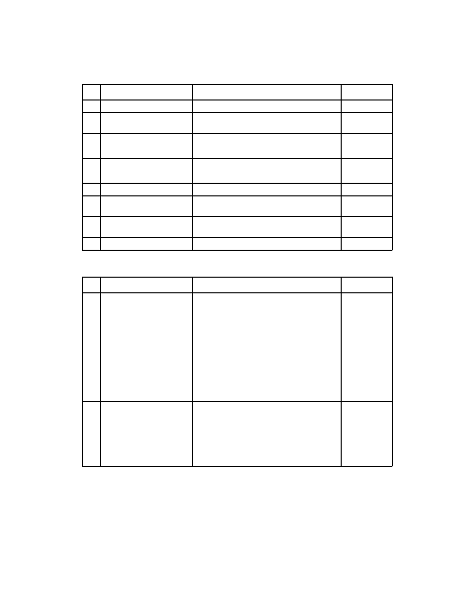
System specifications of the SCU are shown in Table 3.2.
Table 3.2 SCU System Specifications
No
Item
Specification
Remarks
1
DSP
· 32bit X 32bit
48bit
· 14 MHz
· Program RAM 32bit X 256word
· DATA RAM 32bit X 64word X 4
· DMA command
2
DMA
· CPU 3 ch, DSP 1 ch
· 3 level, stack 1 set
· Able to start by interrupt
· Indirect mode
4
Interrupt Control
· Timer (2ch) synchronized with screen
· Interrupt control from external terminal
5
A-bus Control
· A-bus (external bus) bus sizing
· Wait control
· Burst size setting
· Refresh control
6
B-bus Control
· B-bus (internal bus) control
· VDP1, VDP2, SCSP only
14
|

SEGA Confidential
Functions
SCU functions are shown below.
· Data transfer within A-bus, B-bus, and CPU-bus
· Matrix calculations by DSP
· SCU internal interrupt control by interrupt controller
· Data transfer within Main CPU, Internal DSP, A-bus, and B-bus
The SCU has a CPU I/F, A-bus I/F, and B-bus I/F and smoothly executes the inter-
face to multiple processors, which are connected through their respective I/F and
buses. This also allows programs in the main CPU to be transferred to the DSP
within the SCU. Also, while data is being transferred between the A-bus and B-bus,
the work area can be accessed using the CPU-bus from the CPU, and process can be
executed using independent buses in parallel.
· Interrupt Control
Interrupt that extends to other processors executes through the SCU. For example,
to display the volume level on screen, a screen display request interrupt from the
SCSP for the SCU occurs. SCU recognizes the interrupt and issues the interrupt
while synchronized with the screen. Interrupt can then be issued with respect to any
point (dot) on the screen.
Internal DSP
SCU has an internal DSP. This has been provided in order to implement processes
difficult to implement when the load to the main CPU has been excessive.
Operating Frequency
The operating frequency of the DSP inside SCU runs at a frequency of 1/2 the main
CPU. See the Main CPU manual concerning the operating frequency of the main
CPU
.
Saturn Overview Manual
15
|

SEGA Confidential
3.3
VDP1
VDP1 controls sprites.
Compared to conventional systems, drawing speed is exceptionally fast, and be-
cause there is no limit in the number of horizontal sprites, more sprites (characters)
can be displayed. Polygons can be displayed as sprite applications.
System Configuration
The VRAM and two frame buffer screens are connected to VDP1 (Figure 3.2). The
VRAM draw command is set through the SCU from the CPU. VDP1 reads draw
commands from the VRAM and writes (draws) draw data to the frame buffer. Infor-
mation controlling draw is set in the system register inside VDP1. Drawn frame
buffer data is displayed in the TV through VDP2 that controls image display.
CPU
SCU
VRAM
Frame Buffer
Frame Buffer
VDP2
TV
System
Register
VDP1
Figure 3.2 VDP1 System Configuration
16
|

SEGA Confidential
Table 3.3 shows the VDP1 system specifications.
Table 3.3 VDP1 System Specifications
No
Item
Specification
Remarks
1
Texture Parts
Display
· Regular Sprites
(normal sprite, horz. 8~504 dot,
vert. 1~255 dot)
· Expand/Contract Sprite
(any size can be designated by vertical
horizontal 1 dot units)
· Distorted Sprite
(can designate any 4 vertices)
Up-down-left-right
reverse by all sprites is
possible
2
Non-Texture Parts
Display
· Quadrilateral polygon
· Polyline
· Line
You can have a three
-
sided polygon and
polyline if two adjacent
points have the same
coordinates
3
Color Calculation
· Semi-transparent associated parts
· Half brightness
· Shadow
· Mesh
· Gouraud Shading
Gouraud shading can be
combined with semi-
transparent or half
brightness
4
Draw Method
· Double Frame Buffer Method
(Can enlarge, reduce, rotate, and modify
the entire plane of the frame buffer.
Can designate the delete range and
delete data of frame buffer.
Can set write local coordinates.
Can designate clipping of rectangular
area.)
5
Simultaneous Colors
· 16, 64, 128, 256, 32768 colors
16, 64, 128, 256
for high resolution
6
Memory Capacity
· VRAM 4 Mbit
(Character Generator, for all types of
tables)
· Frame buffer 2 Mbit X 2 sides
(Both 2 sides can be used as bit map.
One side is displayed.)
Saturn Overview Manual
17
|

SEGA Confidential
Functions
The main functions of the VDP1 are shown below.
· Draws parts (character line)
· Designates color mode
· Color calculation
· Mesh process
· Designates clipping coordinates and relative coordinates
· Display control of frame buffer
Parts, color mode, and coordinates are controlled by the VRAM command table.
Control of the frame buffer display is done by the system register.
Parts
Parts drawn by VDP1 are divided into texture and non-texture parts depending on
whether or not there is an original picture. Table 3.4 shows part classifications.
Table 3.4 Parts Classification
Classification
Parts Name
Function
Defining Method
Texture Parts
Regular sprite
Character, up-down,
left-right reverse
Read direction of 1
vertex
P
A
R
T
S
Rectangular sprite
Character, up-down,
left-right reverse,
enlarge-reduce,
expand-contract are
possible
Read direction of 2
vertices, or read
direction of fixed
points and width
Transformed sprite
Character, up-down,
left-right reverse,
enlarge-reduce,
expand-contract,
rotation, twisting are
possible
Read direction of 4
vertices
Non-Texture Parts
Polygon
Quadrilateral
Inside is painted solid
4 vertices
Polyline
Quadrilateral
4 vertices
Line
Straight Line
Start and End points
18
|

SEGA Confidential
Texture Parts
Sprites draw character patterns. Character patterns define pixel data as character
pattern tables in VRAM.
Regular Sprites
Normal rectangular sprite.
The pattern of the original picture can be inverted up , down, and left and right.
This can be done in any sprite mode (Figure 3.3).
<
Original
>
<
Drawings
>
Normal
Left-Right
Reverse
Up-down
Reverse
Up-Down
Left-Right Reverse
Figure 3.3 Regular Sprites
Scaled Sprites
For sprites that can be enlarged and reduced, it is only possible to zoom in and out
vertically and horizontally (Figure 3.4).
Expand Horizontally
and Vertically
Expand Vertically
Expand Horizontally
< Original >
Normal
Reduce
Horz.
Reduce Vert
< Drawings >
Figure 3.4 Scaled Sprites
Saturn Overview Manual
19
|

SEGA Confidential
Distorted Sprites
These are sprites that can be distorted. The original picture can be distorted to any
shape by designating four vertices of the character and enlarging, reducing, rotating,
and reversing the picture in any way. If viewed as a polygon, it would be the same
as a texture-mapped polygon.
ORIGINAL
ROTATE
PUSH AT1 POINT
PULL AT1 POINT
TWIST
SHIFT ALL POINTS
CHANGE SHAPE
PUSH IN TOWARD CENTER
Figure 3.5 Distorted Sprites
20
|

SEGA Confidential
Non-Texture Parts
Polygon
This is a four-vertex polygon. It is different with a sprite in that the flat surface
encompassed by the four points is painted over by one color. Sprites have an origi-
nal picture whereas polygons do not.
Polyline
This is a quadrilateral connected by four lines.
Line
This is a line of one color drawn between two points.
POLYGON
LINE
POLYLINE
Figure 3.6 Polygon, Polyline, Line
Display
A common TV is used as a display apparatus. NTSC format is the TV standard of
both Japan and the U.S. Europe uses the PAL format.
TV display is done by reading data from lead of the frame buffer for each frame (1
frame per 1/60 sec.).
Normally, one frame is equal to one field, but one frame that is interlaced is treated
as two fields, allowing the vertical resolution to be doubled (one frame per 1/30
sec.). There is single and double interlace, as shown in Table 3.5.
Table 3.5 Interlace
Saturn Overview Manual
21
Double Interlace
Odd numbered line, a different image is shown by even numbered lines
Single Interlace
Odd numbered line, the same image is shown by even numbered lines
|

SEGA Confidential
Color Mode Designation
There are three methods of designating color modes for textured parts: the color
bank, RGB code, and color look-up. Non-textured parts have pixel data for color
designation.
Color Bank Method
· Combining color bank with 16, 64, 128, and 256 color palette codes, references
colors stored in the VDP2 color RAM.
· VDP2 color palette is selected by the color bank. Color from the color palette is
selected by the palette code.
· 16, 64, 128, 256 colors can be expressed by 1 character.
· Data written by the color bank method is divided and processed by the VDP2
color operation, priority, color bank, and function bits of the palette code.
Color Bank
Palette Code
MSB
LSB
Color Operation
Priority
Figure 3.7 Configuration of the Color Bank Method
RGB Code Generation
Color is expressed by five bits of respective RGB (red, green, blue) luminance.
Color Look-up Table
Colors are selected from the 16 colors defined in the color look-up table. One color
with 16 bits can be of either RGB code or color bank code.
22
|

SEGA Confidential
Color Operation
Gouraud Shading, shadow, half-brightness, and semi-transparent color operations
can be designated by VDP1. Table 3.6 shows the types of color operations.
Table 3.6 Types of Color Operations
Gouraud Shading
Gouraud shading can be applied to parts drawn by RGB, and interpolates color
between polygon vertices which causes a flat surface to appear curved.
A surface can appear to be curved by giving brightness correction values to the four
vertices of a polygon and applying Gouraud shading within these four vertices.
Gouraud shading can be applied to polylines and lines as well. Figure 3.6 shows an
example of Gouraud shading.
TYPE
DESCRIPTION
Semi-transparent
A foundation at half brightness is added to the original at half
brightness. The result is drawn in the frame buffer.
Half-Brightness
An object at half the brightness of the original picture is drawn
in the frame buffer. The foundation cannot be seen because i
is written over and the brightness of the original is reduced to
half.
Shadow
The foundation at half-brightness is re-drawn in the frame
buffer. Here, a shadow of the character shape in the original
can be created. The character of the original is used only in th
shape of the shadow and color data is ignored.
Gouraud Shading
An object in the original picture to which Gouraud shading is
applied is drawn in the frame buffer.
Gouraud Shading
Semi-transparent
The brightness of an object in the original picture to which
Gouraud shading is applied is reduced to half, and foundation
at half-brightness is added. The result is drawn in the frame
buffer.
Gouraud Shading
Half Brightness
The brightness of an object in the original picture to which
Gouraud shading is applied is reduced to half, and the object i
drawn in the frame buffer.
Saturn Overview Manual
23
|

SEGA Confidential
Figure 3.8 Gouraud Shading
Mesh Process
Mesh can be applied to all parts. A checkered pattern (every other dot) is drawn to
the part in which the mesh is applied.
0 1 2 3 4 5 6 7 8 9
0
1
2
3
4
5
6
7
8
9
: not painted
: painted
"X coordinate value + Y coordinate
value" is painted only for even
numbered pixels; odd numbered
pixels are skipped and not written.
Figure 3.9 Mesh Process
24
|

SEGA Confidential
Clipping
Clipping allows only the set display area to be drawn and cuts away any excess.
Clipping includes system clipping that sets the system draw area, and user clipping
that enables any setting by the software.
System Clipping
System clipping is always in effect while drawing. and the inside of the set area is
drawn (see Figure 3.10).
Lower Right Coordinate
System Clipping Area
TV
(0,0)
System clipping can be designatedby
fixing the upper left coordinate (0,0)and
defining the lower right coordinate
Figure 3.10 System Clipping
User Clipping
User clipping can be selected by the software. Choose whether to make user clip-
ping effective for each part, or the inside or outside of the user clipping set area of
the effective area.
Lower Right Coordinate
Upper Left
Coordinate
(0,0)
User Clipping Area
TV
User clipping area can be
designated by selecting the
verticies of the upper left and
lower right coordinates.
Figure 3.11 User Clipping
Saturn Overview Manual
25
|

SEGA Confidential
Frame Buffer
· The frame buffer is divided into two screens, the display frame buffer and draw
frame buffer. Read/Write access from the SCU to the frame buffer is performed
only for the draw frame buffer. The display frame buffer becomes a back-end
bank and cannot be accessed.
· By reading the frame buffer, the read start coordinate and next dot to be read can
enlarge, reduce, and rotate the entire frame buffer surface by giving X and Y
direction displacement, which designates the location.
26
|

SEGA Confidential
3.4
VDP2
VDP2 determines priority of display of the scroll screens and the entire screen (in-
cluding sprites). Simultaneous display of scroll screens has been expanded to a
maximum of five screens. A screen can be moved up, down, left, and right, and
rotated. Priority (display priority order) can be programmably set on each character.
System Configuration
VDP2 has VRAM connected to it and color RAM built-in. Image data is defined
from the CPU through the SCU to VRAM and color RAM.
Data defined in VRAM is read according to settings of the register and becomes
image data of each scroll screen. This data, VDP1, as well as image data sent from
the external image circuits determine the display priority order according to the
register setting, then become display image data. Display image data is converted to
display color data and output to the TV (Figure 3.12).
CPU
SCU
VRAM
VDP1
TV
Register
VDP2
Color
RAM
External Image
Circuit
(optional)
Figure 3.12 VDP2 System Configuration
Saturn Overview Manual
27
|

SEGA Confidential
Table 3.7 VDP2 System Specifications
No
Item
Specification
Remarks
1
TV Screen
· Horizontal Resolution
Select from 320, 352, 640, 704 pixels
· Vertical Resolution
Select from 224, 240, 256 pixels
(for non-interlace)
Select from 448, 480, 512 pixels
(for Interlace)
Vertical resolution of 256
pixels and 512 pixels are
for PAL only.
2
Character
· Character Size
Select from 1 X 1 cell and 2 X 2 cell
· Number of character colors
Select from 16, 256, 2048, 32768, and
16,770,000 colors.
Bit map format is also
possible.
3
Normal Scroll
Screen
· Max. no. of simultaneous screens is 4
· Scrolls horizontally and vertically
· Can line scroll
· Scrolls vertical cells
· Reduces to 1/4, enlarges to 256X
· Mosaic function
4
Rotation Scroll
Screen
· Max. no. of simultaneous screens is 2
· Can Enlarge, Reduce, Rotate
· Rotation parameter can be switched
inside screen
· Special Screen processing by
coefficient table
Normal scroll screen can
not be displayed when 2
screens are displayed
5
Windows
· Normal window 2 screens
· Sprite window 1 screen
· Line window possible
6
Priority
· Priority of each screen is programmable
· Priority can be switched in character
units and dot units
7
Screen Operation
· Color operation for up to 4 screens is
possible
· Color operation rate 32 steps
· Color offset function
· Shadow function
28
|
SEGA Confidential
Functions
VDP2 has a scroll function for controlling the display of the scroll screen, and a
priority function for determining the display priority order (Figure 3.13).
Scroll Functions
Magnify and Reduce
Rotation
Line Scroll
Vertical Cell Scroll
Mosaic Process
Window
Priority Functions
Determine Priority
Color Operation
Color Offset
Shadow
Figure 3.13 Scroll, Priority Functions
Scroll Functions
Scroll has a scroll screen for displaying pictures and windows for display control.
· Scroll Screen
Scroll screen includes a normal scroll screen that can change the number of
displayable screens, and a rotation scroll screen that can rotate a screen.
Table 3.8 shows the functions of the normal scroll screen and rotation scroll screen,
and number of character colors.
Saturn Overview Manual
29
|

SEGA Confidential
Table 3.8 Scroll Screen Functions
· Enlarge/Reduce Function
Enlarge and reduce the entire screen horizontally and vertically. Reduced display
horizontally limits the number of screens.
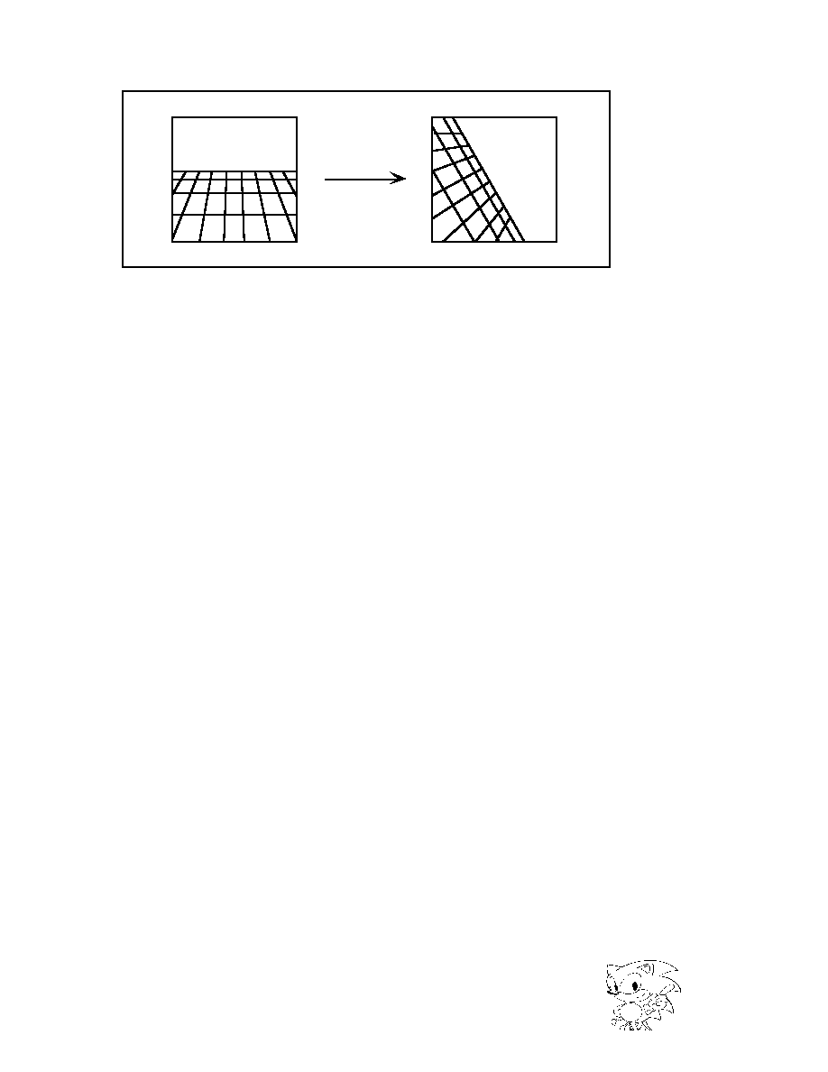
· Line Scroll Function
Scroll up, down, right, and left each line as well as enlarge and reduce horizontally.
This creates the feeling of distance, such as the road of a driving game.
· Vertical Scroll Function
Scroll up and down in units of horizontal cells. It can create depth as in a vertical
scroll game.
· Mosaic Function
All scroll screens are divided horizontally and vertically, and the color of upper-left
dots in each area are displayed per dots in that area.
Function
Normal Scroll Screen
Rotation Scroll Screen
Screen 0
Screen 1
Screen 2
Screen 3
Screen 0
Screen 1
Enlarge/Reduce
1/4 X ~ 256 X
no
any factor
Rotation
no
yes
Line Scroll
yes
yes
no
no
no
Vertical Cell Scroll
yes
yes
no
no
no
Mosaic Process
yes
yes
(only in horizontal)
Displays Bit Map
yes
yes
no
no
yes
no
Character Color
Number
Select from
16
256
2048
32768
16.77 mil.
Select from
16
256
2048
32768
Select from
16
256
Select from
16
256
Select from
16
256
2048
32768
16.77 mil.
Select from
16
256
2048
32768
16.77 mil.
30
|

SEGA Confidential
Area C
Area D
Area B
Area A
Horizontal direction
Mosaic Size
Vertical direction
Mosaic Size
The color of the dot in the upper
left corner of each area is used
in all dots within that area.
Rotation Function
· Rotation Display
The rotation scroll screen rotates along the coordinate axes (X, Y, Z axes) and the
screen axis vertical to the TV screen. Two surfaces can be displayed at the same
time.
Z axis
X axis
Y axis
X axis Rotation
Y axis Rotation
Z axis Rotation
Figure 3.14 Mosaic Pattern
Figure 3.15 Image Modification by Axis Rotation
Saturn Overview Manual
31
|
SEGA Confidential
Figure 3.16 Image Modification by Screen Axis
· Rotation
Rotation calculation is done by the hardware according to designated parameters.
This means that rotation display can be done without straining the CPU load.
Twisted images can be displayed since coordinates can be calculated and different
values applied to each dot.
· Simultaneous Display by Screen Division
The image of two screens can be displayed by showing one screen of the rotation
scroll screen.
Scroll Screen Structure
The two scroll screen formats are the cell format and the bit map format. The cell
format, as in conventional home game devices, displays an arrangement of cells.
The bit map format, as with the personal computer, displays a picture that corre-
sponds to each dot on a screen.
· Cell Format
The cell format scroll screen is a picture pattern consisting of cells (eight horizontal
dots by eight vertical dots), character patterns (an arrangement of cells), pages (an
arrangement of character patterns), planes (an arrangement of pages), and maps (an
arrangement of maps). Figure 3.17 shows the structure of a cell format scroll screen.
32
|

SEGA Confidential
Cell
Page
Plane
Map
Character
Pattern
H8 dots X
V8 dots
H1 cell X
V1 cell
or
H2 cells X
V2 cells
32 X 32
or
64 X 64
character
patterns
(64X64 cells)
H1 page X
V1 page
or
H2 pages X
V1 page
or
H2 pages X
V2 pages
H2 plains X
V2plains
(Normal Scroll Screen)
or
H4 plains X
V4plains
(Rotation Scroll Screen)
NOTE: V = vertical
H = horizontal
Figure 3.17 Cell Format Scroll Screen
· Bit Map Format
The bit map scroll screen consists of a bit map pattern 512 dots or 1024 dots horizon-
tally and 256 dots or 512 dots vertically in size. Figure 3.18 shows the configuration
of the bit map scroll screen.
Bit Map
NOTE: V = vertical
H = horizontal
1 dot
H 512 X V 256 dots
H 512 X V 512 dots
H 1024 X V 256 dots
or
H 1024 X V 512 dots
Figure 3.18 Bit Map Scroll Screen and Data Setting Relationship
Windows
Windows are classified into three types depending on the way the area is designated
(coordinate designation).
· Normal Rectangular Window
Designated by two coordinate points: start and end.
· Normal Line Window
Designated by the start and end points of each line coordinate.
· Sprite Window
Designated by sprite character patterns.
Saturn Overview Manual
33
|

SEGA Confidential
Inside
Window
Inside
Window
Outside
Window
Outside
Window
Outside
Window
TV Screen
TV Screen
TV Screen
Normal Rectangle Window
Normal Line Window
Sprite Window
Inside Window
Figure 3.19 Windows
Priority Functions
The display priority order of sprites and scroll screens is determined by a 3-bit
priority number. The sprite priority number can set a maximum of eight values; one
of which is designated by character units.
Determining Priority
The scroll screen priority number is designated in normal surface units. (This can be
changed by character units or dot units using special priority function.)
transparent
transparent
transparent
Top Image
Second Image
Third Image
Priority
Number=6
Priority
Number=4
Priority
Number=2
Priority
Number=1
Figure 3.20 Priority Function
· Special Priority Function
Priority numbers that correspond to each scroll screen can be changed by character
or dot units. This function the priority of only the area within the scroll screen to be
changed, which causes one scroll screen to appear like as more than one screen.
34
|

SEGA Confidential
Color Calculation Function
By adding multiple screens of color data, the color calculation function produces an
effect that makes the back screen appear to be seen through the front screen. This is
normally done by two screens, the top image and the second image, but can be done
with up to four screens if the expanded color calculation function is used.
transparent
transparent
Priority Number = 4
Priority Number = 2
Back
Screen
Figure 3.21 Color Calculation Function
· Line Color Screen Insert
The line color screen forces the top image part of the designated screen to be inserted
as the second image, and induces color calculation. The pre-inserted second image
becomes the third image in the area of the inserted line color screen, and the third
images drops one to become the fourth image. Figure 3.22 shows insertion of the
line color screen.
Saturn Overview Manual
35
|

SEGA Confidential
top image
second image
third image
fourth image
line color screen
back screen
back screen
back screen
transparent
transparent
transparent
screen the line color screen
has been inserted into
screen the line color screen
has been inserted into
Priority number =6 Priority number =4
Priority number =2
Priority number =1
Figure 3.22 Insertion of the Line Color Screen
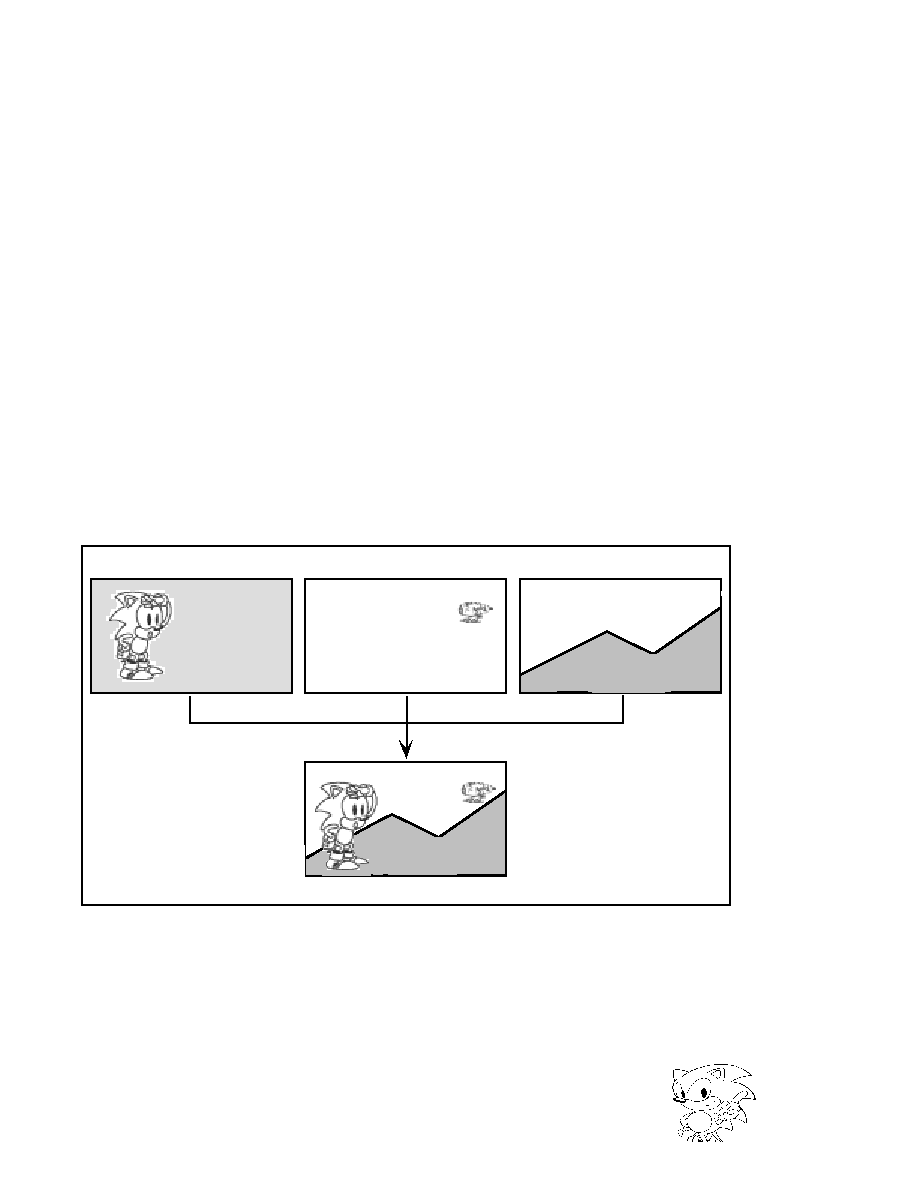
Shadow Function
The shadow calculation function adds a shadow in the shape of the sprite character
on all screens.
+
=
Frame Buffer Data
Scroll Screen
Output Screen
Shadow Sprite
Normal Sprite
transparent
Figure 3.23 Shadow Function
· Blur-Calculation Function
The blur-calculation function adds the horizontal color data of one designated screen
at a fixed rate, and is able to create an effect of a blurred distant background.
36
|

SEGA Confidential
Screen A
Screen B
Screen C
transparent
transparent
Screen A
Screen C
Screen A
Screen B
Priority number = 6
Priority number = 4
Priority number = 2
Screen designated
to be blur-calculated
Top Image
Second Image
Blur-Calculated
Screen C
Screen B
Color Operation
Display Image
Color Function used in Screen C
Replaced as a result of
blur-calculation on
screen C
Screen B
Second Image
Screen C
Blur-Calculated
Screen C
The sum of color data is forced to be as second image in the area where the top or
second image is the designated screen. The blur-calculated picture can be displayed
by performing color calculation on the second and top images.
Color Offset Function
The color offset function displays and adds (or subtracts) the offset value for the
screen color data, and is used in fade-in and fade-out. Designate whether to use the
color offset function in each screen.
Figure 3.24 Blur-Calculation Function
Saturn Overview Manual
37
|

SEGA Confidential
3.5
SCSP
SCSP is custom sound LSI that unites PCM (FM) sound generation with a sound
only DSP. The goal of the audio function is to provide higher tone quality with all
interfaces for increasing expandability. Capable of creating many sounds, the opera-
tion part provides a performance that rivals that of a synthesizer. The DSP can
create multiple sound fields, such as each type of sound field play as well as the
special effects of 3D sound positioning.
System Configuration
The main CPU, sound CPU, sound memory, and D/A converter are all connected to
the SCSP. In the sound system, these can operate independent of the main processor.
The main CPU transfers the sound (CPU, DSP) program and wave form data to the
SCSP sound memory through the SCU. The sound CPU transfers wave form data to
the register inside the SCSP. SCSP reads delayed data for producing sound memory
wave form data as well as the effect. The audio is mixed and output as sound
through a D/A converter.
SCU
Sound CPU
MC68EC000
S C S P
D/A Convertor
Sound Memory
(DRAM)
Interface
PCM(FM)
DSP
MIXER
CPU Program
PCM Sound Data
DSP Delayed Data
Figure 3.25 SCSP System Configuration
38
|

SEGA Confidential
System Specifications
Table 3.9 shows the SCSP system specifications.
Table 3.9 SCSP System Specifications
Functions
The main functions of the SCSP are listed below.
· Frequency control
· Volume control
· FM operation
· LFO (Low Frequency Oscillator) modulation function
· Digital / Audio mixing
· Effect from DSP (reverb)
No
Item
Specifications
Remarks
1
Sampling Frequency
· 44.1 KHz
2
Audio Synthesis System
· PCM, FM Format
3
Audio Process Slot Number
· 32 slots
4
Wave Form Data Format
· 8-bit, 16-bit formats
2'S complement
5
Each function type
· Envelope
· Loop Process
· LFO
6
Effect from internal DSP
· Reverb, Chorus, etc.
7
Other functions
· DMAC ......................... 1ch
· Timer ............................ 3ch
· MIDI ............................. IN/OUT each 1
· External D/A Input ....... Stereo1 system
Saturn Overview Manual
39
|
SEGA Confidential
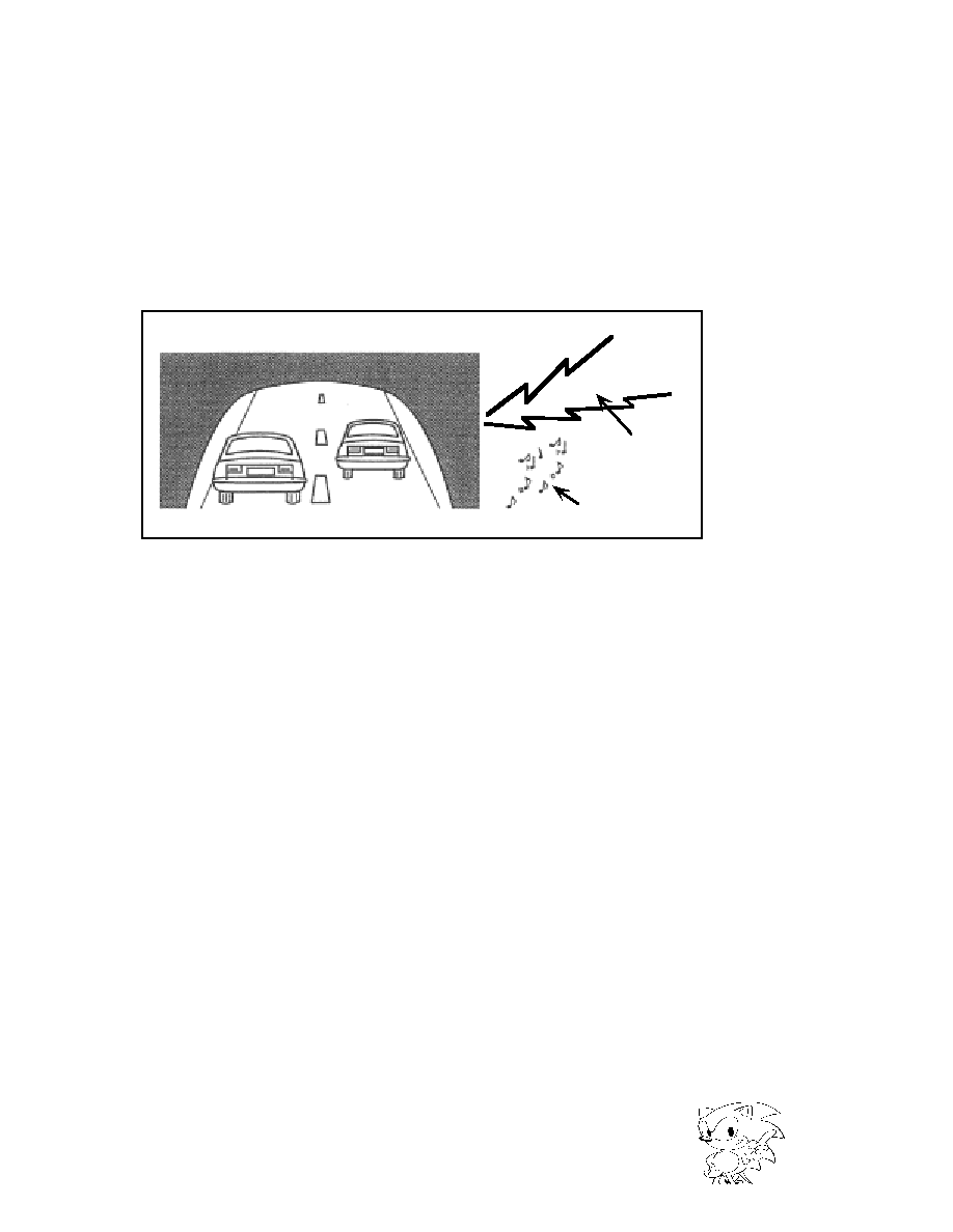
Effect
Because the SCSP DSP can create multiple sound fields, it is possible to have differ-
ent settings for BMG sound and game sound.
For example, in a racing game, reverb would be applied to the concert grounds as
BGM while reverb could be applied at the same time in producing an atmosphere
inside a tunnel for the game.
roarrrrr
Reverb applied to
create a tunnel
atmosphere
Effect applied to
BGM (CD voice)
Figure 3.26 Tunnel and BGM Reverb
In the DSP, the effect can be applied to CD audio because the audio signals from the
sound generator, and sound signals from the CD are input. Because the CD output
level can be controlled through the SCSP, the sound signal from the sound generator
and CD can be balanced and therefore the sound from the sound source will still be
audible without being "hidden" by the CD sound. Thus, concealing the CD sound
will not conceal the sound of the sound generator.
40
|

SEGA Confidential
Sound Position
With a high performance digital mixer, the SCSP can control the positions of all
sounds in real time. As a result, effective sounds can be produced on the screen with
character positions. This process can be done by the DSP as well. In this case, when
the character moves slowly, the sound orientation will move smoothly because more
intricate settings can be made. A sense of depth (distance) can be created by adding
reverb to this positioning.
L
R
Sense
ofdistanc
Fixed Position (pan)
pachinn
pachinn
pachinn
A sense of distance can be created by
changing the echo according to the
distance. This includes fixed positions (pan)
also.
Figure 2.27 Tennis Game Example
Besides this, indoors, outdoors, and wide open spaces can be expressed depending
on the type of reverb. Also, the type of reverb can also be set for all conditions, such
as a hall, stage room, steel plate, etc.
Saturn Overview Manual
41
|

SEGA Confidential
3.6
CD-ROM
The CD-ROM system has its own CPU and buffer RAM, and can operate indepen-
dently of the main system. By setting in advance conditions from the main system,
flexible buffer management that suits the application configuration is attained.
System Configuration
The CD-ROM system operates only by giving commands through CD I/F from the
main system. The sub-CPU interprets commands from the main system, controls the
CD-ROM drive and CD buffer, reads data, and plays video and audio. Audio and
video playing employs the MPEG international video compression standard, and
uses the exclusive "MPEG/Video LSI" as well as "MPEG / Audio LSI." The system
configuration is shown in Figure 3.28.
The sub-CPU, CD buffer, frame buffer, C/D I/F are connected to the MPEG / Video.
Compressed image data is received from the CD buffer and regeneration image data
is written (drawn) to the frame buffer. Drawn frame buffer data carries out the effect
according to register settings and displays in the display device through VDP2 the
controls screen display; or it is transferred to VDP1 and VDP2 VRAM through CD I/
F and SCU.
MPEG / Audio receive compressed audio data from the CD buffer and outputs
stereo 1ch audio data. This audio data is output through the SCSP as sound.
SCSP
VDP2
SCU
CD I/F
MPEG
Video
Frame
Buffer
CD Buffer
CD Drive
MPEG
Audio
SubCPU
(SH-1)
Audio
Image
TV
<Main System>
A-bus
B-bus
Speakers
<CD-ROM System>
Figure 3.28 CD-ROM System Configuration
42
|
SEGA Confidential
CD-ROM system specifications are shown in Table 3.10, and CD drive specifications
are shown in Table 3.11.
Table 3.10 CD-ROM System Specifications
Table 3.11 CD Drive Specifications
No
Item
Specifications
Remarks
1
G/A Register width
16 bit
2
Seek Time
400 msec (1/3 access time, double speed
rotation time)
3
Rotation Speed
Normal time: 620~1680 rpm
2X speed: 1240~3360 rpm
4
CD Read Speed
Normal speed: 75 sectors/sec = 150KB/sec
2X speed: 150 sectors/sec = 300KB/sec
5
Tray Open & Close Method Top loading
6
Memory Capacity
RAM 512KB (for CD buffer) ROM 64KB (for
BIOS) RAM 512KB (for MPEG)
7
Data Transfer Speed
Max. 8MB/sec, max. 4MB/sec while MPEG is
in operation
8
LED
Flashes according to CD operation status
No
Item
Specifications
Remarks
1
CD Play
Track/Index designation play
Frame address (in absolute time) designation
play
Play restarts (Cancels pause, controls pick-up
movement)
Repeat play
able to control CD-DA and CD-ROM by
commands of identical format
Scan regeneration
Retrieve subcode
2
Other
Corresponds to Multi-session
Corresponds to Emphasis
Decode and error correction corresponding
to CD-ROM XA
(Subheader recognition, ECC process, Read
retry process)
Saturn Overview Manual
43
|

SEGA Confidential
Functions
The main functions of the CD-ROM system are shown below.
· Stream select
· Parallel processing
· MPEG functions
-Video play
-Pause screen play (high detail, JPEG)
-Window function
-Visual effect function
(mosaic, shading, Chroma key, fade in / fade out)
- play function
-Pause, freeze, frame feed, slow motion
-MPEG buffer function
CD-ROM system first stores data read from the CD-ROM to the CD buffer. The
stored data reads/writes to the main system or MPEG in response to commands
from the main system. Figure 3.29 shows the data flow of the CD-ROM system.
CD-ROM
MPEG Buffer
MPEG Decoder
CD buffer
(buffer section)
MPEG Frame Buffer
VDP2
Data transfer Register
Host
MPEG Register
Play
Read Write
CD Read = Read
Copy Move
Write
Decode
Display
Image Data
Retrieve
Write
Retrieve
CD Block
Host
Write
Figure 3.29 CD-ROM System Data Flow
44
|

SEGA Confidential
Stream Select
Data flow from the CD-ROM is called a stream. A stream has audio data, image
data, and program data. The stream select function selects the classification of data
and sends it to the main system and MPEG (Figure 3.30). Control content of the
stream select function is shown below.
· Stream data accumulates in the CD buffer and is selected in response to the
data classification.
· Data from devices such as a CD-ROM and MPEG decoder are controlled
uniformly.
· Stream select conditions are set by command.
CD-ROM XA
Select
Buffer
Video
Audio
Main
System
V : Video
A : Audio
D : Data
Data
V
A
D
D A V D A V
Figure 3.30 Stream Select Function
Parallel Processing
The CD-ROM system reads streams, it also selects streams and controls the CD drive
independently of the main system. Further, parallel processing can be done since
more than one stream selection mechanism is set.
Saturn Overview Manual
45
|

SEGA Confidential
MPEG Function
MPEG plays animation with sound added.
Image data is compressed to 1/50 and audio data is compressed to 1/10 before
being played. Therefore, 74 minutes can be recorded on a CD. An exclusive LSI
allows a game with animation (movie) of high image quality to be played without
overloading the CPU.
MPEG / Video Function
Saturn's MPEG/Video has various special functions that are exclusively customized
for Saturn.
Window Function
As shown in Figure 3.31, this function cuts out part of the image played and displays
it at any size on the TV screen. This function allows the display position of the
MPEG play image and display size to be changed, to select and display one of sev-
eral screens, and zoom in, and zoom out.
Image from VDP1, 2
Expressions
such as "open
window" are
allowed
Animation (object 1)
Animation (object 3)
Animation (object 2)
Animation (object 4)
MPEG Play Images
Figure 3.31 Window Function
46
|

SEGA Confidential
Original Image
24 bit, full color
Mosaic
Mosaic size horizontal direction
Mosaic size
vertical direction
The color of the dot in the upper left
corner of each area is used in the
dots of the entire area.
+
+
+
4
+
+
+
4
+
+
+
+
4
+
4
+
Shading
Displays average of right, bottom,
and lower right dots
Horizontal Vertical
Interpolation
Displays average of 4 corner dots
Interpolation Function
The MPEG play image is a maximum 352 X 240 dots horizontally, while vertical
interpolation can be displayed at a resolution of a maximum 704 X 480 dots to pro-
vide a smooth display with less flickering.
Shading Function
Displays a color data average of four dots that adjoin horizontally and vertically, and
can produce a distant background shading effect.
Figure 3.32 Interpolation, Shading, Mosaic Functions
Saturn Overview Manual
47
|
SEGA Confidential
Mosaic Function
The MPEG play image is divided horizontally, vertically, and at a designated size.
The color of the dot in the upper left of each area indicates the color of all dots in
that area. Horizontal and vertical can be independently designated up to a full
screen size.
Fade Function
This is a display function that gives magnification to the coloring signal and screen
brightness, and is used for fade-in and fade-out. Because this isn't a method of
adding and subtracting offset values, only the brightness can be correctly changed.
Further, by changing the coloring signal, the monochrome display or displayed
color can be deepened.
Chroma Key
As shown in Figure 3.33, this function plays animation that has transparent dots.
The chroma key is a technique of filming an object in front of a blue background,
taking out all parts that are not blue, then placing those parts in a separate picture.
MPEG animated images can be used only on background with the existing MPEG
LSI, but the chroma key function lets Saturn superimpose and display MPEG ani-
mated images on sprite and scrolls.
TV Screen
Blue Background
MPEG Screen
Sprite Screen
Scroll Screen
Figure 3.33 Chroma Key Function
48
|

SEGA Confidential
Screen Retrieve Function
Animated images played by MPEG are retrieved to the main system by this func-
tion, and are handled as sprites, used as texture data, and displayed using the VDP1
and VDP2 functions. Furthermore, this function playing of multiple animations.
The amount of MPEG animated data is 50 times the amount of data from a CD, and
because the transfer speed is faster than the transfer speed from a CD buffer, this
function can be used to rewrite texture data at high-speeds.
High Detail Pause Function
This function displays a 704 x 480 dot high detail pause screen. Full color high detail
images cannot be displayed by the main system (full color is up to 352 x 240 dots),
but if the high detail pause function is used, an image with Saturn's maximum
number of color can be displayed.
Pause Function, Freeze Function
The pause function can pause the animation at any frame, and can run in slow
motion as well as frame by frame.
The freeze function memorizes animation at any frame (image memory) and allows
strobe playback.
Branch Play Function
MPEG accumulates compressed image data in the CD buffer memory and plays
animation during CD seek (track search). As a result, animation will continue play-
ing even when jumping to another animation track. The screen will not pause as
with LD.
In MPEG, the branch playback where branch point cannot be determined is
achieved. Furthermore, loop play, which repeats the same animation, can be done.
Saturn Overview Manual
49
|

SEGA Confidential
MPEG / Audio Function
Audio data played by MPEG/Audio is sent to the SCSP by the same path as a CD-
DA (Music CD), and can perform various effects.
Variable Compression Rate
The compression rate can be selected in response to the use; you can choose from a
compression of 1/3.5 ~ 1/21. If the 1/21 compression is used, 50 hours of audio can
be recorded on a CD. Even with huge RPG and ADV, all dialogue and narration can
be performed with audio.
On Memory Play Function
MPEG / Audio can compress to 1/3.5 ~ 1/21. When using half of the
4 Mbit of CD buffer memory for MPEG/Audio by using a compression of 1/21, 64
seconds of audio can be played without accessing the CD. As a result, audio play
can be done without waiting. Furthermore, several short dialogues can be con-
nected for long conversations.
Corresponding Standards
Table 3.12 shows the standards that correspond to the CD-ROM system.
Table 3.12 Corresponding Standards
Standard
Description
CD-DA
The standard name of sound entered on a CD is base on the REDBOOK
international standard. Sampling frequency 44.1 KHz, quantumization bit
16-bit stereo.
CD-G, CDEG
Records data such as graphics data in the music CD format area.
Employs 16 color display and CD-DA sound quality.
CD-ROM
The standard has been established to enable recording of computer data
with the same physical format as a music CD (CD-DA). Based on YELLOW
BOOK international standard.
CD-ROM XA
This is an expanded CD format with a record format that makes possible
interleave recording for concurrent playing of video and audio.
EB
(electronic book)
CD-ROM software record format that is employed by the Sony Data Discma
(electronic book player).
Photo-CD
System that displays photographs through a monitor such as a television.
Up to 100 photographs can be recorded on a CD; the same photograph ca
be enlarged and reduced.
Video CD
(Karaoke CD)
Records video that has been compressed by MPEG. A maximum of 74
minutes can be recorded on a CD, and a maximum of 2000 high detail pau
pictures can be played.
50
|

SEGA Confidential
3.7
Other Items
SMPC
SMPC resets the entire Saturn system when the reset button is pressed or the power
turned on. The command from SH-2 turns on or off the peripheral LSI inside of
Saturn, sets and retrieves the calendar and time, and collects data from peripherals.
The clock change command switches between a horizontal resolution of 320 or 352
dots.
Power On Reset
Reset Switch
SCU
VDP1
VDP2
SCSP
PLL
MC68EC000
PAD
SH-2
(master)
SH-2
(slave)
Sound Reset
System Reset
NMI
RES
NMI
*Switch
Inside Saturn
command
data
reset
clock switch
SMPC
RES
(* Peripheral I/O terminal can be directly controlled from the SH-2 side.)
Figure 3.34 SMPC System Configuration
Saturn Overview Manual
51
|

SEGA Confidential
Functions
The main functions of SMPC are shown in Table 3.13.
Table 3.13 SMPC Functions
PAD
Table 3.14 shows the digital PAD specifications for Saturn.
Table 3.14 Saturn Digital PAD Specifications
RTC
(Real Time Clock)
· Sets and retrieves time and date form SH-2
· Battery back-up function
· Automatically revises the date, day of the week,
hour/minutes/seconds.
S M
(System Management)
· ON/OFF of Sound CPU
· ON/OFF of master SH-2 and slave SH-2
· Controls system reset
· Switches clocks (PLL switch)
· Power ON reset
· When Saturn is ON, Saturn system is reset by
pressing the
reset switch.
PC
(Peripheral Control)
· Automatically collects peripheral data such as
control pad
and mouse.
· Supports Megadrive and Genesis peripherals (3
button, 6 button, 4 player adapter, mouse).
PAD Type
Specifications
Saturn Standard PAD
Buttons: up, down, left, right, A, B, C, X, Y, Z, L, R, start.
52
|

SEGA Confidential
INDEX
B
Bit map format 33
Branch play function 49
C
C3 iii
Cartridge I/F 9
CD-ROM 42
CD-ROM drive 10
CD-ROM drive specifications 43
CD-ROM system data flow 44
CD-ROM system configuration 42
CD-ROM system specifications 42
Cell format 32
Cell format scroll screen 33
Chroma key function 48
Clipping v, 25
Color bank method 22
Color calculation function 35
Color look-up table 22
Color offset function 37
Color operation 23
Compression rate variation 50
Configuration of Color bank method 22
Corresponding standards 50
CPU 6, 11
CPU specifications 11
D
D/A converter 10
Determining priority 34
Display (VDP1) 21
Double density interlace 21
DSP iii
E
Effect 40
Effect Data v
Encode 9
F
Fade function 48
Regular sprite 19
Frame buffer 26
Freeze function 49
Functions (CD-ROM) 44
Functions (SCSP) 38
Functions (SCU) 15
Functions (VDP1) 18
Functions (VDP2) 29
Saturn Overview Manual
53
|

SEGA Confidential
G
Gouraud shading iii, 23, 24
H
Hardware specifications <main system> 6
Hardware specifications <sub system> 6
High detail pause function 49
High Resolution iv
I
Image change by image axis 32
Image change by rotation axis 31
Image change by screen axis 32
Interlace iii, 21
Interpolation function 47
Interpolation, Shading, Mosaic Functions 47
Interrupt control (SUC) 15
IPL v
L
Line 21
Line and texture parts 21
Line color screen insert 35, 36
Line scroll function 30
M
Enlarge/Reduce function (VDP2) 30
Enlarge/Reduce Sprite (VDP1) 19
MC68EC000 8
Mesh process 24
Mosaic function 30, 48
Mosaic pattern 31
MPEG/Audio function 50
MPEG/Video function 46
MPEG functions 46
MPEG iv, 10
N
Normal line window 33
Normal rectangular window 33
O
On memory play function 50
Operating frequency (SCU) 15
54
|

SEGA Confidential
P
PAD 52
PAD I/F 9
PAL format v
Parallel processing 45
Parts classification 18
Parts iv
Perspective iv
Pause function 49
PCM iv
Pixel iii
PLL v
Polygon 21
Polyline 21
Priority function 34
R
RAM 6, 8
Related manuals ii
Reverb v
RGB code generation 6, 8
Rotation calculation 32
Rotation display 31
Rotation function 31
S
Saturn digital PAD specifications 52
Screen retrieve function 49
Scroll function 29
Scroll screen 29
Scroll screen configuration 32
Scroll screen function 30
Scroll, Priority functions 29
SCSP 9, 38
SCSP system configuration 38
SCSP system specifications 39
SH-2 8
Shading calculation function 36, 37
Shading function 47
Shadow function 36
Simultaneous display by screen division 32
Single density interlace 21
SMPC 8, 12, 51
SMPC functions 52
SMPC system specifications 51
Special priority function 34
Sprite iv
Sprite window 33
Stream select mechanism 45
Stream selection 45
System clipping 25
System configuration (CD-ROM) 42
System configuration (SCSP) 38
Saturn Overview Manual
55
|

SEGA Confidential
System configuration (VDP2) 27
System configuration 7
System specifications (SCSP) 38
T
Texture mapping iv
Texture part 19
Transformed sprite 20
Tunnel and BGM reverb 40
Types of color calculation 23
U
User clipping 25
V
VDP1 9, 16
VDP1 system configuration 16
VDP1 system specifications 17
VDP2 9, 27
VDP2 system configuration 27
VDP2 system specifications 28
Vertical scroll function 30
W
Window 33, 34
Window function 46
56
|